Nissan Rogue Service Manual: Component parts
Component Parts Location
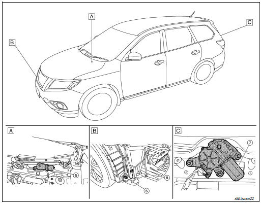
- View of cowl area (with cowl top cover removed)
- RH front of vehicle (with front bumper fascia removed)
- View with back door finisher removed
|
No. |
Component |
Function |
| 1 | Combination switch (Wiper and washer switch) | Refer to WW-8, "FRONT WIPER AND WASHER SYSTEM : System Description".
Refer to BCS-76, "Removal and Installation". |
| 2 | Combination meter | Transmits the vehicle speed signal to BCM via CAN communication. |
| 3 | IPDM E/R |
Refer to WW-6, "Component Parts Location" |
| 4 | BCM |
Refer to WW-6, "Component Parts Location". |
| 5 | Front wiper motor | Refer to WW-7, "Front wiper motor". |
| 6 | Front and rear washer motor | Refer to WW-7, "Washer pump". |
| 7 | Rear wiper motor | Refer to WW-7, "Rear wiper motor". |
| 8 | Washer Fluid Level Switch | Transmits the washer fluid level switch signal to the combination meter. |
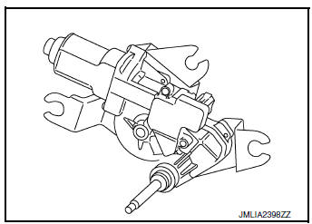
Front wiper motor
- Controls front wiper operation with IPDM E/R control.
- Transmits front wiper stop position signal to IPDM E/R.
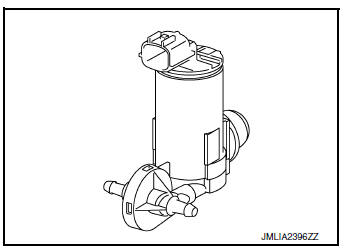
Washer pump
- Washer fluid is sprayed according to washer switch states.
- Switching between front washer and rear washer is performed according to the voltage polarity change to washer pump.
Washer fluid level switch
Detects that washer fluid level is low and transmits washer fluid level switch signal to combination meter.

Rear wiper motor
- Controls rear wiper operation with BCM control.
- Transmits rear wiper stop position signal to BCM.

 System
FRONT WIPER AND WASHER SYSTEM
FRONT WIPER AND WASHER SYSTEM : System Diagram
FRONT WIPER AND WASHER SYSTEM : System Description
OUTLINE
FRONT WIPER CONTROL (BASIC)
BCM detects the co ...
Other materials:
Precaution
Precaution for Supplemental Restraint System (SRS) "AIR BAG" and "SEAT
BELT
PRE-TENSIONER"
The Supplemental Restraint System such as “AIR BAG” and “SEAT BELT PRE-TENSIONER”,
used along
with a front seat belt, helps to reduce the risk or severity of injury to the
...
System description
COMPONENT PARTS
Component Parts Location
Right rear wheel area
Instrument panel
Engine compartment
Left side of instrument panel (view
with trim panel removed)
No.
Part
Function
1
Optical sensor
Refer to EXL-140, "Optical Senso ...
Luggage room lamp
Removal and Installation
REMOVAL
Insert a suitable tool (A) into the gap between the luggage lower
finisher (RH) (2) and the top of luggage room lamp (1) to release
the pawl.
: Pawl
Disconnect the harness connector from the luggage room lamp and remove.
INSTALLATION
Installati ...
