Nissan Rogue Service Manual: Charging system preliminary inspection
Diagnosis Procedure
1.CHECK BATTERY TERMINALS CONNECTION
Check if battery terminals are clean and tight.
Is the inspection result normal? YES >> GO TO 2.
NO >> Repair battery terminal connection. Confirm repair by performing complete Charging system test using EXP-800 NI or GR8-1200 NI (if available). Refer to the applicable Instruction Manual for proper testing procedures.
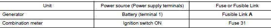
2.CHECK FUSE
Check for blown fuse and fusible link.
Is the inspection result normal? YES >> GO TO 3.
NO >> Replace the blown fuse or fusible link after repairing the affected circuit.
3.CHECK DRIVE BELT TENSION
Check drive belt tension. Refer to MA-13, "DRIVE BELTS : Tension Adjustment".
Is the inspection result normal? YES >> Inspection End.
NO >> Repair as needed.

 Power generation voltage variable control system operation
inspection
Power generation voltage variable control system operation
inspection
Diagnosis Procedure
Regarding Wiring Diagram information. Refer to CHG-7, "Wiring Diagram".
CAUTION:
When performing this inspection, always use a charged battery that has completed
the ...
Other materials:
DTC/Circuit diagnosis
C1201 AWD CONTROL UNIT
DTC Description
DTC DETECTION LOGIC
DTC No.
CONSULT screen terms
(Trouble diagnosis content)
DTC detecting condition
C1201
CONTROLLER FAILURE
(Control unit failure)
Malfunction has occurred inside AWD control unit.
POSSIBLE CAUSE
Int ...
Towing load/specification
TOWING LOAD/SPECIFICATION CHART
U.S. and Canada
Maximum Towing Capacity*1
1,100lb.
(500 kg)
Maximum Tongue Load
110 lb.
(50 kg)
Maximum Gross Combined Weight Rating
5,291 lb.
(2,400 kg)
*1: The towing capacity ...
C1144 incomplete steering angle sensor adjustment
DTC Logic
DTC DETECTION LOGIC
DTC
Display Item
Malfunction detected condition
Possible causes
C1144
ST ANG SEN SIGNAL
When neutral position adjustment of steering angle
sensor is not complete.
Harness or connector
Steering angle sensor
&n ...
