Nissan Rogue Service Manual: Center console assembly
Exploded View
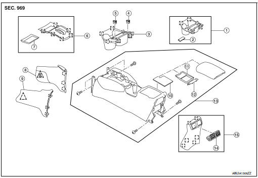
- Center console cup holder (without heated seats)
- Coin tray insert
- Center console cup holder (with heated seats)
- Front heated seat switch (RH)
- Front heated seat switch (LH)
- Shift selector finisher
- Shift selector finisher mat
- Center console side finisher (RH)
- Center console side finisher (LH)
- Center console tray
- Center console bin mat
- Center console rear brace finisher
- Center console assembly
- Rear center ventilator grille
- Center console rear finisher
 Metal clip
 Clip
Clip
 Pawl
Pawl
Removal and Installation
REMOVAL
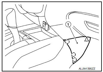
- Release clips and pawls using a suitable tool and remove center console side finisher (1) (LH/RH).
: Pawl
: Clip
NOTE: RH side shown; LH similar.
- Remove shift selector knob. Refer to TM-194, "Exploded View".
- Remove cluster lid C. Refer to IP-21, "Removal and Installation".
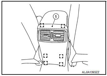
- Release clips using a suitable tool and remove center console
rear finisher (1).: Metal clip
- Remove center console screws (A).
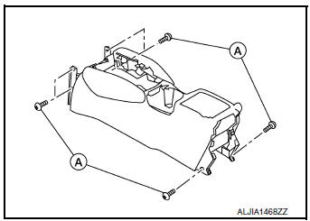
- Disconnect the harness connectors and remove center console.
INSTALLATION
Installation is in the reverse order of removal.
 Steering column covers
Removal and Installation
REMOVAL
Release gap hider (1) pawls from the steering column upper
cover (2).
: Pawl
Remove steering column cover screws (A)
NOTE:
Rotate steering w ...
 Cluster lid A
Removal and Installation
REMOVAL
Remove instrument lower panel LH. Refer to IP-22, "Removal and
Installation".
Remove instrument finisher A. Refer to IP-15, "INSTR ...
Other materials:
Diagnosis system (BCM) (without intelligent key system)
COMMON ITEM
COMMON ITEM : CONSULT Function (BCM - COMMON ITEM)
APPLICATION ITEM
CONSULT performs the following functions via CAN communication with BCM.
Direct Diagnostic Mode
Description
Ecu Identification
The BCM part number is displayed.
Self Diagnostic ...
P1572 brake pedal position switch
DTC Description
DTC DETECTION LOGIC
NOTE:
This self-diagnosis has the one trip detection logic. When malfunction A is
detected, DTC is not stored
in ECM memory. And in that case, 1st trip DTC and 1st trip freeze frame data are
displayed. 1st trip
DTC is erased when ignition switch OFF. And ...
Preparation
Special Service Tool
The actual shape of the tools may differ from those illustrated here.
Tool number
(TechMate No.)
Tool name
Description
—
(J-43897-18)
Oxygen sensor thread cutter
Reconditioning the exhaust system threads
before installing ...
