Nissan Rogue Service Manual: C1155 brake fluid level switch
DTC Logic
DTC DETECTION LOGIC
| DTC | Display Item | Malfunction detected condition | Possible causes |
| C1155 | BR FLUID LEVEL LOW | When brake fluid level low signal is detected |
|
DTC CONFIRMATION PROCEDURE
1.CHECK SELF-DIAGNOSTIC RESULT
 With CONSULT.
- Turn ignition switch OFF to ON and wait 1 minute or more.
- Perform self-diagnostic result.
Is DTC C1155 detected? YES >> Proceed to diagnosis procedure. Refer to BRC-99, "Diagnosis Procedure".
NO >> Inspection End.
Diagnosis Procedure
Regarding Wiring Diagram information, refer to BRC-57, "Wiring Diagram".
1.CHECK BRAKE FLUID LEVEL
- Turn the ignition switch OFF.
- Check brake fluid level. Refer to BR-8, "Inspection".
Is the inspection result normal? YES >> GO TO 2.
NO >> Refill brake fluid. Refer to BR-16, "Drain and Refill".
2.CONNECTOR INSPECTION
- Turn ignition switch OFF.
- Disconnect combination meter connector M76 and brake fluid level switch connector E63.
- Check connectors and terminals for deformation, disconnection, looseness or damage.
Is the inspection result normal? YES >> GO TO 3.
NO >> Repair or replace as necessary.
3.CHECK BRAKE FLUID LEVEL SWITCH
Check brake fluid level switch. Refer to BRC-100, "Component Inspection".
Is the inspection result normal? YES >> GO TO 4.
NO >> Replace reservoir tank. Refer to BR-28, "Disassembly and Assembly".
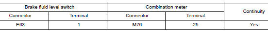
4.CHECK BRAKE FLUID LEVEL SWITCH CIRCUIT
- Turn the ignition switch OFF.
- Disconnect brake fluid level switch harness connector.
- Disconnect combination meter harness connector.
- Check continuity between brake fluid level switch harness connector and combination meter harness connector.
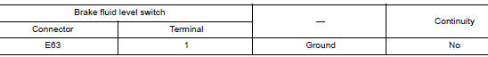
- Check continuity between brake fluid level switch harness connector and ground.
Is the inspection result normal? YES >> GO TO 5.
NO >> Repair or replace malfunctioning components.
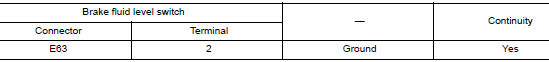
5.CHECK BRAKE FLUID LEVEL SWITCH GROUND CIRCUIT
Check continuity between brake fluid level switch harness connector and ground.
Is the inspection result normal? YES >> GO TO 6.
NO >> Repair or replace malfunctioning components.
6.CHECK COMBINATION METER
Check if indication and operation of combination meter are normal. Refer to MWI-8, "METER SYSTEM : System Description".
Is the inspection result normal? YES >> Replace ABS actuator and electric unit (control unit). Refer to BRC-136, "Removal and Installation".
NO >> Replace combination meter. Refer to MWI-82, "Removal and Installation".
Component Inspection
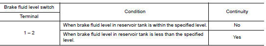
1.CHECK BRAKE FLUID LEVEL SWITCH
- Turn the ignition switch OFF.
- Disconnect brake fluid level switch harness connector.
- Check continuity between terminals of brake fluid level switch.
Is the inspection result normal? YES >> Inspection End.
NO >> Replace reservoir tank. Refer to BR-28, "Disassembly and Assembly".
 C1144 incomplete steering angle sensor adjustment
DTC Logic
DTC DETECTION LOGIC
DTC
Display Item
Malfunction detected condition
Possible causes
C1144
ST ANG SEN SIGNAL
When neutral position adjustment of steering angl ...
 C1160 DECEL G SEN SET
DTC Logic
DTC DETECTION LOGIC
DTC
Display Item
Malfunction detected condition
Possible causes
C1160
DECEL G SEN SET
When calibration of yaw rate/side/decel G sensor is ...
Other materials:
Basic inspection
INSPECTION AND ADJUSTMENT
ADDITIONAL SERVICE WHEN REPLACING CONTROL UNIT (BCM)
ADDITIONAL SERVICE WHEN REPLACING CONTROL UNIT (BCM) : Description
BEFORE REPLACEMENT
When replacing BCM, save or print current vehicle specification with CONSULT
configuration before replacement.
NOTE:
If “Befo ...
P0181 FTT sensor
DTC Description
DTC DETECTION LOGIC
DTC No.
CONSULT screen terms
(Trouble diagnosis content)
DTC detecting condition
P0181
FTT SENSOR
(Fuel temperature sensor ″A″ circuit range/
performance)
A
Rationally incorrect voltage from the sensor is sent ...
Steering gear and linkage
Exploded View
REMOVAL AND INSTALLATION
Cotter pin
Steering gear
Heat shiel
Removal and Installation
REMOVAL
Set the front wheels and tires to the straight-ahead position.
Remove the floor cover. Refer to ST-12, "Exploded View".
Remov ...
