Nissan Rogue Service Manual: Basic inspection
DIAGNOSIS AND REPAIR WORKFLOW
Work Flow
OVERALL SEQUENCE
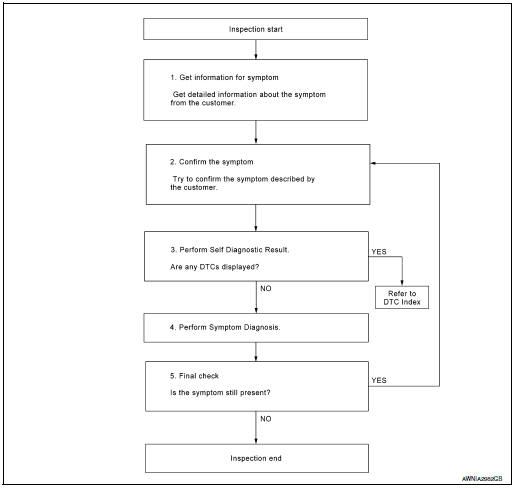
DETAILED FLOW
1.GET INFORMATION FOR SYMPTOM
Get detailed information from the customer about the symptom (the condition and the environment when the incident/malfunction occurred).
>> GO TO 2.
2.CONFIRM THE SYMPTOM
Try to confirm the symptom described by the customer. Verify relation between the symptom and the condition when the symptom is detected.
>> GO TO 3.
3.PERFORM SELF DIAGNOSTIC RESULT
- Turn ignition switch ON and wait for 2 seconds or more.
- Depending on system being diagnosed, perform Self Diagnostic Result for:
- MULTI AV.
- AVM.
Are any DTCs displayed? YES >> Refer to AV-251, "DTC Index" (MULTI AV) or AV-257, "WITHOUT DRIVER ASSISTANCE SYSTEM : DTC Index" (AVM).
NO >> GO TO 4.
4.PERFORM SYMPTOM DIAGNOSIS
Refer to AV-361, "Symptom Table".
>> GO TO 5.
5.FINAL CHECK
Refer to symptom described by the customer in step 1.
Is the symptom still present? YES >> GO TO 2.
NO >> Inspection End.
INSPECTION AND ADJUSTMENT
ADDITIONAL SERVICE WHEN REPLACING AV CONTROL UNIT
ADDITIONAL SERVICE WHEN REPLACING AV CONTROL UNIT : Description
BEFORE REPLACEMENT
When replacing AV control unit, save or print current vehicle specification with CONSULT configuration before replacement.
NOTE: If “Before Replace ECU” cannot be used, use the “After Replace ECU” or “Manual Configuration” after replacing AV control unit.
AFTER REPLACEMENT
CAUTION: When replacing AV control unit, you must perform “After Replace ECU” with CONSULT.
- Complete the procedure of “After Replace ECU” in order.
- If you set incorrect “After Replace ECU”, incidents might occur.
- Configuration is different for each vehicle model. Confirm configuration of each vehicle model.
ADDITIONAL SERVICE WHEN REPLACING AV CONTROL UNIT : Work Procedure
1.SAVING VEHICLE SPECIFICATION
 -CONSULT
Enter “Re/Programming, Configuration” and perform “Before Replace ECU” to save or print current vehicle specification.
NOTE: If “Before Replace ECU” cannot be used, use the “After Replace ECU” or “Manual Configuration” after replacing AV control unit. >> GO TO 2.
2.REPLACE AV CONTROL UNIT
Replace AV control unit. Refer to AV-376, "Removal and Installation".
>> GO TO 3.
3.WRITING VEHICLE SPECIFICATION
 CONSULT
- Enter "Re/Programming, Configuration".
- If “Before Replace ECU” operation was performed, automatically an "Operation Log Selection" screen will be displayed. Select the applicable file from the "Saved Data List" and press “Confirm” to write vehicle specification. Refer to AV-289, "CONFIGURATION (AV CONTROL UNIT) : Work Procedure".
- If “Before Replace ECU” operation was not performed, select "After Replace ECU" or "Manual Configuration" to write vehicle specification. Refer to AV-289, "CONFIGURATION (AV CONTROL UNIT) : Work Procedure".
>> GO TO 4.
4.OPERATION CHECK
Check that the operation of the AV control unit and camera images (fixed guide lines) are normal.
>> Work End.
ADDITIONAL SERVICE WHEN REPLACING AROUND VIEW MONITOR CONTROL UNIT
ADDITIONAL SERVICE WHEN REPLACING AROUND VIEW MONITOR CONTROL UNIT : Description
BEFORE REPLACEMENT
When replacing around view monitor control unit, save or print current vehicle specification with CONSULT configuration before replacement.
NOTE: If “Before Replace ECU” cannot be used, use the “After Replace ECU” or “Manual Configuration” after replacing around view monitor control unit.
AFTER REPLACEMENT
CAUTION: When replacing around view monitor control unit, you must perform “After Replace ECU” with CONSULT.
- Complete the procedure of “After Replace ECU” in order.
- If you set incorrect “After Replace ECU”, incidents might occur.
- Configuration is different for each vehicle model. Confirm configuration of each vehicle model.
ADDITIONAL SERVICE WHEN REPLACING AROUND VIEW MONITOR CONTROL UNIT : Work Procedure
1.SAVING VEHICLE SPECIFICATION
-CONSULT
Enter “Re/Programming, Configuration” and perform “Before Replace ECU” to save or print current vehicle specification.
NOTE: If “Before Replace ECU” cannot be used, use the “After Replace ECU” or “Manual Configuration” after replacing around view monitor control unit. >> GO TO 2.
2.REPLACE AROUND VIEW MONITOR CONTROL UNIT
Replace around view monitor control unit. Refer to AV-387, "Removal and Installation".
>> GO TO 3.
3.WRITING VEHICLE SPECIFICATION
CONSULT
- Enter "Re/Programming, Configuration".
- If “Before Replace ECU” operation was performed, automatically an "Operation Log Selection" screen will be displayed. Select the applicable file from the "Saved Data List" and press “Confirm” to write vehicle specification. Refer to AV-290, "CONFIGURATION (AROUND VIEW MONITOR CONTROL UNIT) : Work Procedure".
- If “Before Replace ECU” operation was not performed, select "After Replace ECU" or "Manual Configuration" to write vehicle specification. Refer to AV-290, "CONFIGURATION (AROUND VIEW MONITOR CONTROL UNIT) : Work Procedure".
>> GO TO 4.
4.OPERATION CHECK
Check that the operation of the around view monitor control unit and camera images (fixed guide lines and predictive course lines) are normal.
>> Work End.
CONFIGURATION (AV CONTROL UNIT)
CONFIGURATION (AV CONTROL UNIT) : Description
Vehicle specification needs to be written with CONSULT because it is not written after replacing AV control unit.
Configuration has three functions as follows:
|
Function |
Description |
| "Before Replace ECU" |
|
| "After Replace ECU" | Writes the vehicle configuration with manual selection. |
| "Select Saved Data List" | Writes the vehicle configuration with saved data. |
CAUTION:
- When replacing AV control unit, you must perform “Select Saved Data List” or "After Replace ECU" with CONSULT.
- Complete the procedure of “Select Saved Data List” or "After Replace ECU" in order.
- If you set incorrect “Select Saved Data List” or "After Replace ECU", incidents might occur.
- Configuration is different for each vehicle model. Confirm configuration of each vehicle model.
- Never perform “Select Saved Data List” or "After Replace ECU" except for new AV control unit.
CONFIGURATION (AV CONTROL UNIT) : Work Procedure
1.WRITING MODE SELECTION
CONSULT
Select “Reprogramming, Configuration” of AV control unit.
When writing saved data>>GO TO 2.
When writing manually>>GO TO 3.
2.PERFORM “SAVED DATA LIST”
CONSULT
Automatically “Operation Log Selection” window will display if “Before Replace
ECU” was performed. Select
applicable file from the “Save Data List” and press “Confirm”.
>> Work End.
3.PERFORM “AFTER REPLACE ECU” OR “MANUAL CONFIGURATION”
CONSULT
- Select “After Replace ECU” or “Manual Configuration”.
- Identify the correct model and configuration list. Refer to AV-290, "CONFIGURATION (AV CONTROL UNIT) : Configuration List".
- Confirm and/or change setting value for each item.
CAUTION: Thoroughly read and understand the vehicle specification. ECU control may not operate normally if the setting is not correct.
- Select “Next”.
CAUTION: Make sure to select “Next”, confirm each setting value and press “OK” even if the indicated configuration of brand new AV control unit is same as the desirable configuration. If not, configuration which is set automatically by selecting vehicle model can not be memorized.
- When "Completed", select "End".
>> GO TO 4.
4.OPERATION CHECK
Confirm that each function controlled by AV control unit operates normally.
>> Work End.
CONFIGURATION (AV CONTROL UNIT) : Configuration List
CAUTION: Thoroughly read and understand the vehicle specification. Incorrect settings may result in abnormal control of ECU.
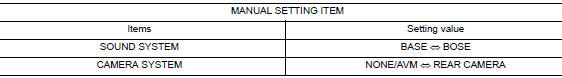
⇔: Items which confirm vehicle specifications
CONFIGURATION (AROUND VIEW MONITOR CONTROL UNIT)
CONFIGURATION (AROUND VIEW MONITOR CONTROL UNIT) : Description
Vehicle specification needs to be written with CONSULT because it is not written after replacing around view monitor control unit.
Configuration has three functions as follows:
|
Function |
Description |
| "Before Replace ECU" |
|
| "After Replace ECU" | Writes the vehicle configuration with manual selection. |
| "Select Saved Data List" | Writes the vehicle configuration with saved data. |
CAUTION:
- When replacing around view monitor control unit, you must perform “Select Saved Data List” or "After Replace ECU" with CONSULT.
- Complete the procedure of “Select Saved Data List” or "After Replace ECU" in order.
- If you set incorrect “Select Saved Data List” or "After Replace ECU", incidents might occur.
- Configuration is different for each vehicle model. Confirm configuration of each vehicle model.
- Never perform “Select Saved Data List” or "After Replace ECU" except for new around view monitor control unit.
CONFIGURATION (AROUND VIEW MONITOR CONTROL UNIT) : Work Procedure
1.WRITING MODE SELECTION
 CONSULT
Select “Reprogramming, Configuration” of around view monitor control unit.
When writing saved data>>GO TO 2.
When writing manually>>GO TO 3.
2.PERFORM “SAVED DATA LIST”
 CONSULT
Automatically “Operation Log Selection” window will display if “Before Replace ECU” was performed. Select applicable file from the “Save Data List” and press “Confirm”.
>> Work End.
3.PERFORM “AFTER REPLACE ECU” OR “MANUAL CONFIGURATION”
 CONSULT
- Select “After Replace ECU” or “Manual Configuration”.
- Identify the correct model and configuration list. Refer to AV-291, "CONFIGURATION (AROUND VIEW MONITOR CONTROL UNIT) : Configuration List".
- Confirm and/or change setting value for each item.
CAUTION: Thoroughly read and understand the vehicle specification. ECU control may not operate normally if the setting is not correct.
- Select “Next”.
CAUTION: Make sure to select “Next”, confirm each setting value and press “OK” even if the indicated configuration of brand new around view monitor control unit is same as the desirable configuration. If not, configuration which is set automatically by selecting vehicle model can not be memorized.
- When "Completed", select "End".
>> GO TO 4.
4.OPERATION CHECK
Confirm that each function controlled by around view monitor control unit operates normally.
>> Work End.
CONFIGURATION (AROUND VIEW MONITOR CONTROL UNIT) : Configuration List
CAUTION: Thoroughly read and understand the vehicle specification. Incorrect settings may result in abnormal control of ECU.
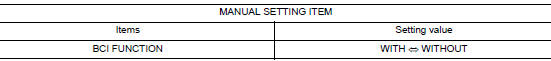
⇔: Items which confirm vehicle specifications
PREDICTED COURSE LINE CENTER POSITION ADJUSTMENT
PREDICTED COURSE LINE CENTER POSITION ADJUSTMENT : Description
Adjust the center position of the predictive course line of the rear view monitor if it is shifted.
PREDICTED COURSE LINE CENTER POSITION ADJUSTMENT : Work Procedure
1.DRIVING
Drive the vehicle straight ahead 100 m (328.1 ft) or more at a speed of 30 km/h (18.6 MPH) or more.
>> End.
CALIBRATING CAMERA IMAGE (AROUND VIEW MONITOR)
CALIBRATING CAMERA IMAGE (AROUND VIEW MONITOR) : Description
- Calibration must be performed after removing/replacing the cameras, removing parts (e.g. front grille, door mirror, and others) mounted on the cameras, or replacing the Around view monitor control unit.
- The use of CONSULT is required to perform calibration or writing of calibration results to the Around view monitor control unit.
- Align the white lines on the road near the vehicle at the boundary
of each camera image by this camera calibration.
The white lines far from the vehicle may not be aligned at the boundary of each camera image. The farther the line, the greater the difference is.
CALIBRATING CAMERA IMAGE (AROUND VIEW MONITOR) : Work Procedure
CALIBRATION FLOWCHART
Following the flowchart shown in the figure, perform the calibration.
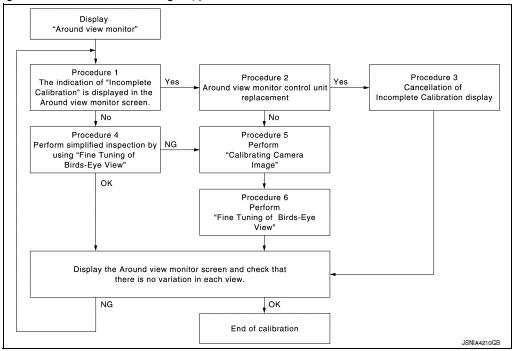
NOTE:
View in the incomplete calibration state is indicated by “ ” on the
around view monitor.
” on the
around view monitor.
CALIBRATION PROCEDURE
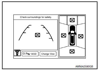
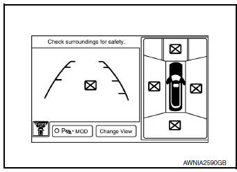
1.AROUND VIEW MONITOR SCREEN CONFIRMATION
Check that there is no indication of “Incomplete calibration”.
Is the “Incomplete calibration” display visible? YES >> GO TO 2.
NO >> GO TO 4.
2.CHECK THAT AROUND VIEW MONITOR CONTROL UNIT IS REPLACED
Check that the around view monitor control unit is replaced.
Is the around view monitor control unit replaced? YES >> GO TO 3.
NO >> GO TO 5.
3.CANCEL THE INDICATION OF INCOMPLETE CALIBRATION (PERFORM THIS ONLY AFTER REPLACING AROUND VIEW MONITOR CONTROL UNIT.)
 CONSULT work support
- On the CONSULT screen, touch “CALIBRATING CAMERA IMAGE (FRONT
CAMERA)”, “CALIBRATING
CAMERA IMAGE (PASS-SIDE CAMERA)”, “CALIBRATING CAMERA IMAGE (DR-SIDE
CAMERA)”, or
“CALIBRATING CAMERA IMAGE (REAR CAMERA)” to accept the selection.
NOTE: To cancel the indication of Incomplete calibration, select items based on the target camera.
- On the adjustment screen of each camera, touch “APPLY” button.
After this, touch “OK” button.
CAUTION:
- Never perform operations other than those mentioned above.
- Never perform “Initialize Camera Image Calibration”.
- Display the around view monitor screen to check that there is no errors, such as deviations among the camera images.
Is there a malfunction? YES >> Calibration End.
NO >> GO TO 1.

4.PERFORM SIMPLIFIED CONFIRMATION/ADJUSTMENT BY “FINE TUNING OF BIRDS-EYE VIEW”
- Put target line 1 on the ground beside each axle using packing tape, etc.
- Put target lines 2 equal to the vehicle total length + approximately 1.0 m (39.3 in) from the vehicle side (right and left) at approximately 30 cm (11.8 in) away from the vehicle (make the line as parallel with the vehicle as possible)
Preparation of simplified target line
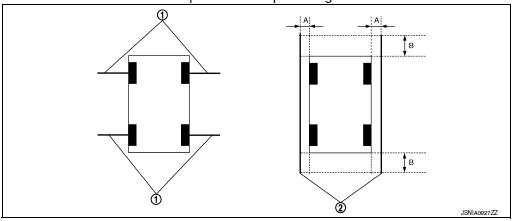
- Target lines 1
- Target lines 2
- Approx. 30 cm (11.8 in)
- Approx. 1.0 m (39.3 in)
- CONSULT work support Touch “FINE TUNING OF BIRDS-EYE VIEW” on the CONSULT screen.
- On the CONSULT screen, touch “SELECT” button to select right or left camera and perform camera calibration as instructed below:
- If the marker on the screen deviates from Target line 1, touch “AXIS X” button and “AXIS Y” button to adjust so that the marker is placed on the Target line 1.
- If Target line 2 is misaligned among the cameras, adjust each camera image to bring Target line 2 into a straight line.
CAUTION: Never adjust the front camera and rear camera. Only adjust the right and left cameras.
Simplified target line adjustment method
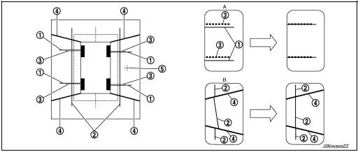
- Target lines 1
- Target lines 2
- Marker for target line 1
- Boundary between cameras
- Crosshairs cursor (mark indicated the selected camera)
- Adjustment method for target lines 1 (right)
- Adjustment method for target lines 2 (right)
- Adjust right and left cameras. Touch "APPLY" on the CONSULT screen to display adjustment results.
- After adjusting right and left cameras, check that the marker is properly placed on the screen and there is no deviation in Target line 1.
NOTE:
- It can be initialized to the NISSAN factory default condition with “Initialize Camera Image Calibration”.
- The adjustment value is cancelled on this mode by performing “Initialize Camera Image Calibration”.
Is the difference corrected? YES >> On the CONSULT screen, touch “OK” button to complete writing to the around view monitor control unit.
NO >> GO TO 5.
5.PERFORM “CALIBRATING CAMERA IMAGE”
Preparation of target line
- Hang a string with a weight as shown in the figure. Put the points FM0, RM0 (mark) on the ground at the center of the vehicle front end and rear end with white packing tape or a pen.
- Route the vinyl string under the vehicle, and then pull and fix it on the point approximately 1.0 m (39.9 in) to the front and rear of the vehicle through the points FM0 and RM0 using packing tape.
Target line preparation procedure 1
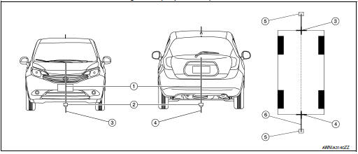
- Thread
- Weight
- Point FM0 (mark)
- Point RM0 (mark)
- Packing tape (to fix the vinyl string)
- Vinyl string
- Put the points FM and RM (mark) 75 cm (29.5 in) from the points FM0 and RM0 individually.
- Route the vinyl string through the points FM and RM using a triangle scale, and then fix it at approximately 1.5 m (59 in) on both sides with packing tape.
- Put the points FL, FR, RL, and RR (mark) to both right and left [vehicle width / 2 + 30 cm (11.8 in)] from the points FM and RM.
Target line preparation procedure 2
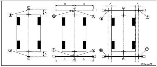
- Point FM
- Point RM
- Triangle scale
- Point FL (mark)
- Point FR (mark)
- Point RL (mark)
- Point RR (mark)
- 75 cm (29.5 in)
- Approx. 1.5 m (59 in)
- 30 cm (11.8 in) [Vehicle width/ 2 + 30 cm (11.8 in) from the points FM and RM]
- Draw the lines of the points FL – RL and FR – RR with vinyl string, and fix it with packing tape.
- Put a mark on the center of each axle, draw vertical lines to the lines of the points FL – RL and FR – RR from the marks on the center of the axle using a triangle scale, and then fix the lines using packing tape.
Target line preparation procedure 3
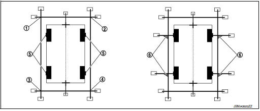
-
Point FL
-
Point FR
-
Point RL
-
Point RR
-
Center position of axle
-
Triangle scale
Perform “Calibrating Camera Image”
 CONSULT work support
- On the CONSULT screen, touch “CALIBRATING CAMERA IMAGE (FRONT CAMERA)”,
“CALIBRATING
CAMERA IMAGE (PASS-SIDE CAMERA)”, “CALIBRATING CAMERA IMAGE (DR-SIDE
CAMERA)”, or
“CALIBRATING CAMERA IMAGE (REAR CAMERA)” to accept the selection.
NOTE: To cancel the indication of Incomplete calibration, select items based on the target camera.
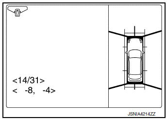
- On the adjustment screen of each camera, adjust the parameter by touching the “AXIS X” button, “AXIS Y” button, and “ROTATE” button to place the calibration marker shown on the camera screen on the target line drawn on the ground.
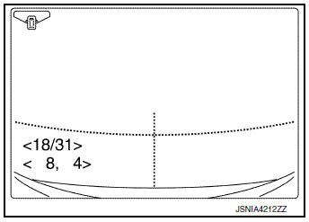
Adjustment range
Rotation direction (Center dial) : 31 patterns (16 on the center)
Upper/lower direction (upper/lower
switch) : −22 – 22
Left/right direction (left/right switch) : −22 – 22
- Touch “APPLY” button on the CONSULT screen. “PRCSNG” is
displayed and adjustment results are shown on the camera screen.
CAUTION: Check that “PRCSNG” is displayed. Never perform other operations while “PRCSNG” is displayed.
- Touch “OK” button on the CONSULT screen. “PRCSNG” is displayed and
adjustment results are written to
the around view monitor control unit.
CAUTION: Check that “PRCSNG” is displayed. Never perform other operations while “PRCSNG” is displayed.
>> GO TO 6.
6.PERFORM “FINE TUNING OF BIRDS-EYE VIEW”
This mode is designed to align the boundary between each camera image that could not be aligned in the “Calibrating Camera Image” mode.
 CONSULT work support
- Select “FINE TUNING OF BIRDS-EYE VIEW” by touching CONSULT screen.
- On the adjustment screen of each camera, adjust the parameter
by touching the “AXIS X” button, “AXIS Y” button”, and
“ROTATE” button to place the calibration marker shown on the
camera screen on the target line drawn on the ground.
NOTE: Touch “SELECT” button on the CONSULT screen to select the target camera.
- Touch “APPLY” button on the CONSULT screen. “PRCSNG” is
displayed and adjustment results are shown on the camera
screen.
CAUTION: Check that “PRCSNG” is displayed. Never perform other operations while “PRCSNG” is displayed.
- Touch “OK” button on the CONSULT screen. “PRCSNG” is displayed and adjustment results are written to the around view monitor control unit.
CAUTION:
- Check that “PRCSNG” is displayed. Never perform other operations while “PRCSNG” is displayed.
- After pressing the “OK” button, never press buttons other than the “BACK” button.
NOTE:
- It can be initialized to the NISSAN factory default condition with “Initialize Camera Image Calibration”.
- The adjustment value is cancelled in this mode by performing “Initialize Camera Image Calibration”.
>> Calibration End.
 Wiring diagram
NAVIGATION WITH BOSE
Wiring Diagram
...
 DTC/circuit diagnosis
U0428 STEERING ANGLE SENSOR
DTC Logic
DTC DETECTION LOGIC
CONSULT Display
DTC Detection Condition
Possible Cause
ST ANG SEN CALIB
[U0428]
Predictive course l ...
Other materials:
CVT fluid cooler system
Cleaning
Whenever an automatic transaxle is repaired, overhauled, or replaced, the CVT
fluid cooler mounted in the
radiator must be inspected and cleaned.
Metal debris and friction material, if present, can be trapped or be deposited
in the CVT fluid cooler. This
debris can contaminate the ...
Rear window defogger relay
Description
Power is supplied to the rear window defogger with BCM control.
Component Function Check
1. CHECK REAR WINDOW DEFOGGER RELAY POWER SUPPLY CIRCUIT
Check that an operation noise of rear window defogger relay [located in fuse
block (J/B)] can be heard when
turning the rear window def ...
Preparation
Special Service Tool
The actual shape of the tools may differ from those illustrated here.
Tool number
(TechMate No.)
Tool name
Description
—
(J-39570)
Chassis Ear
Locating the noise
—
(J-50397)
NISSAN Squeak and Rattle
Kit
...
