Nissan Rogue Service Manual: B terminal circuit
Description
Terminal “B” is constantly supplied with battery power.
Diagnosis Procedure
Regarding Wiring Diagram information, refer to STR-7, "Wiring Diagram".
CAUTION: Perform diagnosis under the condition that the engine cannot start by the following procedure.
- Remove fuel pump fuse.
- Crank or start the engine (where possible) until the fuel pressure is released.
1.CHECK “B” TERMINAL CIRCUIT
- Turn ignition switch OFF.
- Check that starter motor ”B” terminal connection is clean and tight.
- Check voltage between starter motor ”B” terminal and ground.
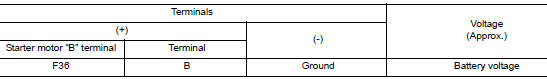
Is the inspection result normal? YES >> GO TO 2.
NO >> Check harness between battery and starter motor for open circuit.
2.CHECK BATTERY CABLE CONNECTION STATUS (VOLTAGE DROP TEST)
- Shift selector lever to ”P” (Park) or ”N” (Neutral) position.
- Check voltage between battery positive terminal and starter motor ”B” terminal.
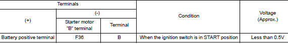
Is the inspection result normal? YES >> GO TO 3.
NO >> Check harness between the battery and starter motor for continuity.
3.CHECK GROUND CIRCUIT STATUS (VOLTAGE DROP TEST)
- Shift selector lever to ”P” (Park) or ”N” (Neutral) position.
- Check voltage between starter motor case and battery negative terminal.
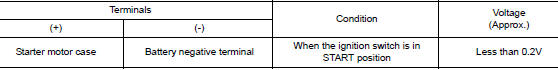
Is the inspection result normal?
YES >> “B” terminal circuit is OK. Further inspection is necessary. Refer to STR-11, "Work Flow (With GR8-1200 NI)" or STR-15, "Work Flow (Without GR8-1200 NI)".
NO >> Check the starter motor case to engine mounting for high resistance.

 S connector circuit
Description
The starter motor magnetic switch is supplied with power when the ignition
switch is turned to the START position
while the selector lever is in the P (Park) or N (Neutral) position.
...
Other materials:
Both doors mirror defogger don’t operate but rear window defogger operates
Diagnosis Procedure
Regarding Wiring Diagram information, refer to DEF-12, "Wiring Diagram".
1. CHECK DOOR MIRROR DEFOGGER FUSE
Check if the following fuse in fuse block (J/B) is blown.
Is the inspection result normal?
YES >> GO TO 2.
NO >> Replace the blown fuse af ...
Using the system
The NISSAN Voice Recognition system allows
hands-free operation of the Bluetooth® Hands-
Free Phone System.
If the vehicle is in motion, some commands may
not be available so full attention may be given to
vehicle operation.
Initialization
When the ignition switch is placed in the ON
posi ...
Hazard warning flasher switch
Push the switch on to warn other drivers when
you must stop or park under emergency conditions.
All turn signal lights flash.
WARNING
If stopping for an emergency, be sure to
move the vehicle well off the road.
Do not use the hazard warning flashers
while ...
