Nissan Rogue Service Manual: Ambient sensor signal circuit
Description
It detects outside air temperature and converts it into a resistance value which is then input into the combination meter.
Diagnosis Procedure
Regarding Wiring Diagram information, refer to MWI-32, "Wiring Diagram".
1.CHECK AMBIENT SENSOR SIGNAL CIRCUIT
- Turn ignition switch OFF.
- Disconnect combination meter connector and ambient sensor connector.
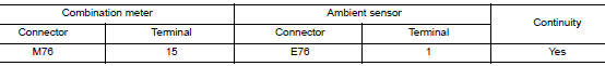
- Check continuity between combination meter harness connector and ambient sensor harness connector.
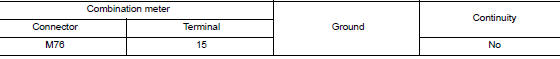
- Check continuity between combination meter harness connector and ground.
Is the inspection result normal? YES >> GO TO 2.
NO >> Repair or replace harness or connector.
2.CHECK AMBIENT SENSOR SIGNAL GROUND CIRCUIT
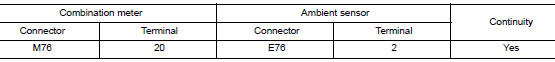
Check continuity between combination meter harness connector and ambient sensor harness connector.
Is the inspection result normal? YES >> Inspection End.
NO >> Repair or replace harness or connector.
Component Inspection
1.CHECK AMBIENT SENSOR
- Turn ignition switch OFF.
- Disconnect ambient sensor connector.
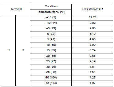
- Check resistance between ambient sensor terminals.
Is the inspection result normal? YES >> Inspection End.
NO >> Replace ambient sensor. Refer to HAC-104, "Removal and Installation".
 Parking brake switch signal circuit
Description
Transmits the parking brake switch signal to the combination meter.
Component Function Check
1.COMBINATION METER INPUT SIGNAL
Start engine.
Check "PKB SW" in ...
 Meter control switch signal circuit
Diagnosis Procedure
Regarding Wiring Diagram information, refer to MWI-32, "Wiring Diagram".
1.CHECK METER CONTROL SWITCH SIGNAL
Turn ignition switch ON.
Check voltage be ...
Other materials:
Exterior and interior lights
Item
Wattage (W)
Bulb No.
Headlight assembly*
High
65
H9
Low
55
H11
Park
5
W5W
Turn
28/8
7444
Sidemarker
5
WY5W
Front fog lights (if so equipped)
55
H11
...
B0021 side curtain air bag module IH
DTC Logic
DTC DETECTION LOGIC
CONSULT name
DTC
DTC detecting condition
Repair order
CURTAIN AIRBAG MODULE LH CIRCUIT
[OPEN]
B0021
LH side curtain air bag module circuit
is open.
Refer to SRC-55, "Diagnosis Procedure".
CURTA ...
Warning/indicator lights
Warning
light
Name
Anti-lock Braking
System (ABS) warning
light
Brake warning light
Charge warning
light
Low tire pressure
warning light
Low windshield
washer fluid warning
light
Master w ...
