Nissan Rogue Service Manual: 1564 ASCD steering switch
DTC Description
DTC DETECTION LOGIC
| DTC No. | CONSULT screen terms (Trouble diagnosis content) | DTC detecting condition |
| P1564 | ASCD SW (ASCD switch) |
|
POSSIBLE CAUSE
- Harness or connectors (ASCD steering switch circuit is open or shorted.)
- ASCD steering switch
- ECM
FAIL-SAFE
Not applicable
DTC CONFIRMATION PROCEDURE
1.CHECK DTC PRIORITY
If DTC P1564 is displayed with DTC P0603, P0604, P0605, P606, P0607, P060A, or P060B, first perform the trouble diagnosis for DTC P0603, P0604, P0605, P606, P0607, P060A, or P060B.
Is applicable DTC detected? YES >> Perform diagnosis of applicable. Refer to EC-93, "DTC Index".
NO >> GO TO 2.
2.PRECONDITIONING
If DTC Confirmation Procedure has been previously conducted, always perform the following procedure before conducting the next test.
- Turn ignition switch OFF and wait at least 10 seconds.
- Turn ignition switch ON.
- Turn ignition switch OFF and wait at least 10 seconds.
>> GO TO 3.
3.PERFORM DTC CONFIRMATION PROCEDURE
- Turn ignition switch ON.
- Wait at least 10 seconds.
- Press MAIN switch for at least 10 seconds, then release it and wait at least 10 seconds.
- Press CANCEL switch for at least 10 seconds, then release it and wait at least 10 seconds.
- Press ACCEL/RES switch for at least 10 seconds, then release it and wait at least 10 seconds.
- Press COAST/SET switch for at least 10 seconds, then release it and wait at least 10 seconds.
- Check DTC.
Is DTC detected? YES >> Proceed to EC-403, "Diagnosis Procedure".
NO >> INSPECTION END
Diagnosis Procedure
1.CHECK DTC PRIORITY
If DTC P1564 is displayed with DTC P0603, P0604, P0605, P606, P0607, P060A, or P060B, first perform the trouble diagnosis for DTC P0603, P0604, P0605, P606, P0607, P060A, or P060B.
Is applicable DTC detected? YES >> Perform diagnosis of applicable. Refer to EC-93, "DTC Index".
NO >> GO TO 2.
2.CHECK ASCD STEERING SWITCH CIRCUIT
 With CONSULT
- Turn ignition switch ON.
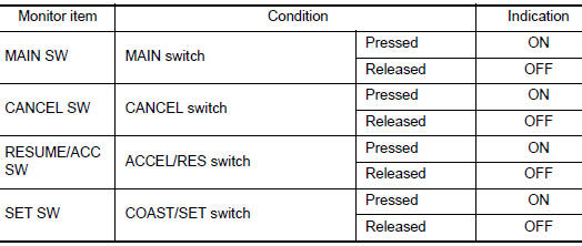
- Select “CANCEL SW”, “RESUME/ACC SW” and “SET SW” in “DATA MONITOR” mode of “ENGINE” using CONSULT.
- Check each item indication as per the following conditions.
 Without CONSULT
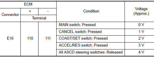
- Turn ignition switch ON.
- Check the voltage between ECM harness connector terminals.
Is the inspection result normal? YES >> GO TO 6.
NO >> GO TO 3.
3.CHECK ASCD STEERING SWITCH GROUND CIRCUIT
- Turn ignition switch OFF.
- Disconnect ECM harness connector.
- Disconnect combination switch (spiral cable) harness connector.
- Check the continuity between combination switch (spiral cable) and ECM harness connector.
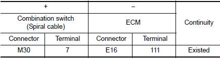
- Also check harness for short to ground and to power.
Is the inspection result normal? YES >> GO TO 4.
NO >> Repair or replace error-detected parts.
4.CHECK ASCD STEERING SWITCH INPUT SIGNAL CIRCUIT
- Check the continuity between ECM harness connector and combination switch.
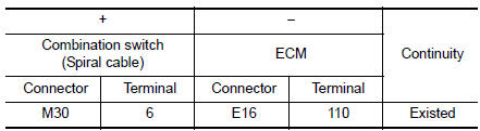
- Also check harness for short to ground and to power.
Is the inspection result normal? YES >> GO TO 5.
NO >> Repair or replace error-detected parts.
5.CHECK ASCD STEERING SWITCH
Refer to EC-405, "Component Inspection".
Is the inspection result normal? YES >> GO TO 6.
NO >> Replace ASCD steering switch. Refer to ST-11, "Removal and Installation".
6.CHECK INTERMITTENT INCIDENT
Refer to GI-41, "Intermittent Incident".
>> INSPECTION END
Component Inspection
1.CHECK ASCD STEERING SWITCH
- Disconnect combination switch (spiral cable) harness connector.
- Check the resistance between combination switch harness connector terminals as per the following conditions.
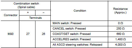
Is the inspection result normal? YES >> INSPECTION END
NO >> Replace ASCD steering switch. Refer to ST-11, "Exploded View".
 P155D generator
DTC Description
DTC DETECTION LOGIC
DTC No.
CONSULT screen terms
(Trouble diagnosis content)
DTC detecting condition
P155D
GENERATOR
(Generator)
ECM receiv ...
 P1568 signal invalid
DTC Description
DTC DETECTION LOGIC
DTC No.
CONSULT screen terms
(Trouble diagnosis content)
DTC detecting condition
P1568
ICC COMMAND VALUE
(Intelligent cruise contro ...
Other materials:
Installing front license plate
Installing front license plate
Use the following steps to mount the front license
plate:
Before mounting the license plate, confirm that
the following parts are enclosed in the plastic
bag:
License plate bracket
License plate bracket (J-nut) screws x 2
License plat ...
Side air spoiler
Exploded View
Side air spoiler
Clip
Removal and Installation
REMOVAL
Remove side air spoiler bolts (A).
1: Side air spoiler
B: Clips
Release clips using suitable tool (A) and remove side air spoiler
(1).
: Clips
INSTALLATION
Installation is in the rev ...
Removal and installation
FRONT AIR CONTROL
Removal and Installation
REMOVAL
Release the front air control clips and pawls using a suitable
tool.
: Metal clip
: Pawl
Disconnect the harness connector from the front air control (1)
and remove.
INSTALLATION
Installation is in the reverse order of ...
