Nissan Rogue Service Manual: Removal and installation
EXHAUST SYSTEM
Exploded View
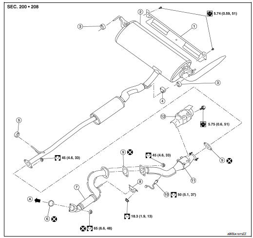
- Exhaust diffuser
- Muffler assembly
- Mounting rubber
- Mounting rubber
- Mounting rubber
- Ring gasket
- Front exhaust tube
- Mounting rubber
- Exhaust gasket
- Oxygen sensor 2
- Center exhaust tube
- Catalyst shroud
- To exhaust manifold and three way catalyst
Removal and Installation
WARNING:
- Perform the procedures with the exhaust system fully cooled down to avoid injury from the hot exhaust system.
- Be careful not to cut your hand on the catalyst shroud edge.
CAUTION: Use genuine NISSAN exhaust system parts or equivalent, which are specifically designed for heat resistance, corrosion resistance, and shape.
REMOVAL
- Remove exhaust system components using power tool.
- Remove heated oxygen sensor 2 using suitable tool.
INSTALLATION
Installation is in the reverse order of removal.
CAUTION:
- Do not reuse exhaust gasket.
- Do not reuse nuts securing front exhaust tube to exhaust manifold and three way catalyst.
- Do not allow foreign substances to contact new exhaust gasket.
- Be sure to install ring gasket to prevent catching when tightening.
- Do not reuse ring gasket.
- Ensure flexible portion of front exhaust tube is free from deformation.
- During installation, take care not to deform mounting rubbers. After installing, the mounting rubbers shall show no excessive movement, twisting, or elongation. To facilitate installation, a neutral detergent may be used.
- Mounting rubbers installed at either side of muffler are to be installed in accordance with paint marks. Mounting rubber at LH side is installed with white paint mark facing forward. Mounting rubber at RH side is installed with white paint mark facing rearward.
- Do not spray exhaust tubes, muffler, heated oxygen sensor 2, or catalyst shroud with anti-corrosive wax.
- If catalyst shroud is badly deformed, repair or replace it. If deposits, such as mud, pile up on the catalyst shroud, remove them.
- When installing catalyst shroud, avoid large gaps or interference between catalyst shroud and exhaust pipe.
- Temporarily tighten fasteners and check each part for interference with other components, and then tighten fasteners to specification.
- Discard any heated oxygen sensor 2 which has been dropped.
- Before installing a new heated oxygen sensor 2, clean exhaust system threads using Tool.
Oxygen sensor thread cleaner : J-43897-18
- Tighten heated oxygen sensor 2 using suitable tool. Do not use impact wrench.
- Do not over tighten heated oxygen sensor 2. Doing so may cause damage to the heated oxygen sensor 2, resulting in the “MIL” coming on.
- Remove deposits from the sealing surface of each connection. Connect them securely to avoid exhaust gas leaks.
Inspection
INSPECTION AFTER INSTALLATION
- Check clearance between tail tube and rear bumper is even.
- With engine running, check exhaust tube joints for gas leakage and unusual noises.
- Check to ensure that mounting brackets and mounting rubbers are installed properly and free from undue stress. Improper installation could result in excessive noise and vibration.
 Periodic maintenance
EXHAUST SYSTEM
Inspection
Check exhaust pipes, muffler, and mounting for improper attachment,
leakage, cracks, damage or deterioration.
If anything is found, repair or replace damaged par ...
 Starting System
...
Other materials:
Difference between predicted and actual
distances
Backing up on a steep uphill
When backing up the vehicle up a hill, the distance
guide lines and the vehicle width guide
lines are shown closer than the actual distance.
For example, the display shows 3 ft (1.0 m) to the
place A , but the actual 3 ft (1.0 m) distance on
the hill is the p ...
Steering wheel
Exploded View
Steering wheel
Removal and Installation
REMOVAL
Set the front wheels and tires in the straight-ahead position.
Remove driver air bag module. Refer to SR-12, "Removal and
Installation"
Remove steering wheel bolt.
Disconnect harn ...
U1010 control unit (CAN)
Description
Air bag diagnosis sensor performs self-tests on key ON. If CAN communication
failure within control unit is
detected, DTC is set.
DTC Logic
DTC DETECTION LOGIC
CONSULT name
DTC
DTC detecting condition
Repair order
CAN CONTROL UNIT FAILURE
...
