Nissan Rogue Service Manual: Rear window defogger power supply and ground circuit
Description
Heats the heating wire with the power supply from the rear window defogger relay to prevent the rear window from fogging up.
Component Function Check
1. CHECK REAR WINDOW DEFOGGER
Check that the heating wire of rear window defogger is heated when turning the rear window defogger switch ON.
Is the inspection result normal? YES >> Rear window defogger is OK.
NO >> Refer to DEF-26, "Diagnosis Procedure".
Diagnosis Procedure
Regarding Wiring Diagram information, refer to DEF-12, "Wiring Diagram".
1. CHECK FUSES
Check if any of the following fuses in fuse block (J/B) are blown.
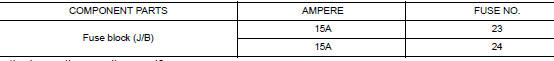
Is the inspection result normal? YES >> GO TO 2.
NO >> Replace the blown fuse after repairing the affected circuit.
2. CHECK REAR WINDOW DEFOGGER POWER SUPPLY CIRCUIT
- Turn ignition switch ON.
- Check voltage between fuse block (J/B) connector and ground
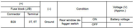
Is the inspection result normal? YES >> GO TO 3.
NO >> Perform rear window defogger relay diagnosis. Refer to DEF-24, "Diagnosis Procedure".
3. CHECK POWER SUPPLY CIRCUIT
- Turn ignition switch ON.
- Check voltage between rear window defogger connector and ground.
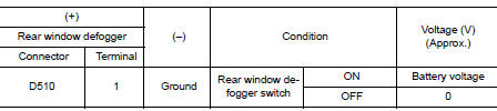
Is the inspection result normal? YES >> GO TO 4.
NO >> GO TO 5.
4. CHECK GROUND CIRCUIT
- Turn ignition switch OFF.
- Disconnect rear window defogger.
- Check continuity between rear window defogger connector and ground.
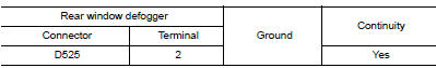
Is the inspection result normal? YES >> GO TO 6.
NO >> Repair or replace harness.
5. CHECK HARNESS CONTINUITY
- Turn ignition switch OFF.
- Disconnect fuse block (J/B).
- Check continuity between fuse block (J/B) connector and rear window defogger condenser connector.
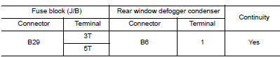
Is the inspection result normal? YES >> Replace rear window defogger condenser. Refer to DEF-41, "Removal and Installation".
NO >> Replace or repair harness.
6. CHECK FILAMENT
Check filament.
Refer to DEF-27, "Component Inspection".
Is the inspection result normal? YES >> Refer to GI-41, "Intermittent Incident".
NO >> Repair filament. Refer to DEF-39, "Inspection and Repair".
Component Inspection
1. CHECK FILAMENT
Check the filament for damage or open circuits.
Refer to DEF-39, "Inspection and Repair".
Is the inspection result normal? YES >> Inspection End.
NO >> Repair filament. Refer to DEF-39, "Inspection and Repair".
 Rear window defogger relay
Description
Power is supplied to the rear window defogger with BCM control.
Component Function Check
1. CHECK REAR WINDOW DEFOGGER RELAY POWER SUPPLY CIRCUIT
Check that an operation noise of rear ...
 Driver side door mirror defogger
Description
Heats the heating wire with the power supply from the rear window defogger
relay to prevent the door mirror
from fogging up.
Component Function Check
1. CHECK DOOR MIRROR DEFOGGER LH ...
Other materials:
Liftgate release
WARNING
Always be sure the liftgate has been
closed securely to prevent it from opening
while driving.
Do not drive with the liftgate open. This
could allow dangerous exhaust gases
to be drawn into the vehicle. For additional
information, refer to “Ex ...
Vehicle recovery (freeing a stuck vehicle)
FRONT
Securely install the vehicle recovery hook stored with jacking tools.
Check that the hook is properly secured in the stored place after use.
WARNING:
Stand clear of a stuck vehicle.
Never spin your tires at high speed. This could cause them to
explode and result in ser ...
Power seat switch
Exploded View
Seat cushion outer finisher
Power seat switch
Removal and Installation
REMOVAL
NOTE:
LH shown, RH similar.
Using a suitable tool release clips and remove seat cushion
outer finisher (1).
: Clip
Disconnect harness connector from power seat switch.
...
