Nissan Rogue Service Manual: Power seat switch
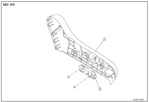
Exploded View

- Seat cushion outer finisher
- Power seat switch
Removal and Installation
REMOVAL
NOTE: LH shown, RH similar.
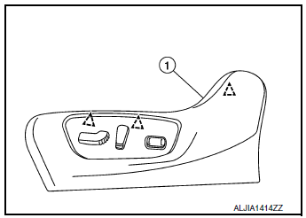
- Using a suitable tool release clips and remove seat cushion
outer finisher (1).
 : Clip

- Disconnect harness connector from power seat switch.
- Remove screws and power seat switch.
INSTALLATION
Installation is in the reverse order of removal.
CAUTION:
- Visually check the clips for deformation and damage during installation. Replace with new ones if necessary.
- When installing seat cushion outer finisher, check that clips are securely placed into seat cushion frame holes.
 Third row seats
Exploded View
Seatback board (RH)
Seatback trim (RH)
Seatback pad (RH)
Seat cushion trim (RH)
Seat cushion pad (RH)
Seat cushion silencer (LH/RH)
Seat hinge fi ...
 Lumbar support switch
Exploded View
Seat cushion outer finisher
Lumbar support switch
Clip
Pawl
Removal and Installation
REMOVAL
Using a suitable tool release clips and remove seat cushi ...
Other materials:
Precaution
Precaution for Supplemental Restraint System (SRS) "AIR BAG" and "SEAT
BELT
PRE-TENSIONER"
The Supplemental Restraint System such as “AIR BAG” and “SEAT BELT PRE-TENSIONER”,
used along
with a front seat belt, helps to reduce the risk or severity of injury to the
...
Periodic maintenance
REAR WHEEL HUB AND HOUSING
Inspection
INSPECTION
Make sure the conditions (looseness, back lash) of each component and
component conditions (wear, damage)
are normal.
WHEEL HUB AND BEARING INSPECTION
Move wheel hub and bearing in the axial direction by hand. Make
sure there is no ...
Wiring diagram
Wiring Diagram
...
