Nissan Rogue Service Manual: P0712 transmission fluid temperature sensor A
DTC Description
DTC DETECTION LOGIC
| DTC | CONSULT screen terms (Trouble diagnosis content) | DTC detection condition |
| P0712 | FLUID TEMP SENSOR A (Transmission Fluid Temperature Sensor A Circuit Low) | When all of the following conditions are satisfied and this state is
maintained
for 5 seconds:
|
POSSIBLE CAUSE
- Harness or connector (CVT fluid temperature sensor circuit is shorted to ground)
- CVT fluid temperature sensor
FAIL-SAFE
- Engine coolant temperature when engine start: Temp. ‚Č• 10¬įC (50¬įF)
- Start is slow
- Acceleration is slow
- Engine coolant temperature when engine start: ‚ąí35¬įC (‚ąí31¬įF) ‚ȧ Temp. < 10¬įC (50¬įF)
- Selector shock is large
- Start is slow
- Acceleration is slow
- Engine coolant temperature when engine start: Temp. < ‚ąí35¬įC (‚ąí31¬įF)
- Selector shock is large
- Start is slow
- Acceleration is slow
DTC CONFIRMATION PROCEDURE
1.PREPARATION BEFORE WORK
If another "DTC CONFIRMATION PROCEDURE" occurs just before, turn ignition switch OFF and wait for at least 10 seconds, then perform the next test.
>> GO TO 2.
2.PERFORM DTC CONFIRMATION PROCEDURE
- Start the engine and wait for 10 seconds or more.
- Check the first trip DTC.
Is ‚ÄúP0712‚ÄĚ detected? YES >> Go to TM-121, "Diagnosis Procedure".
NO-1 >> To check malfunction symptom before repair: Refer to GI-41, "Intermittent Incident".
NO-2 >> Confirmation after repair: INSPECTION END
Diagnosis Procedure
1.CHECK CIRCUIT BETWEEN TCM AND CVT UNIT
- Turn ignition switch OFF.
- Disconnect TCM connector and CVT unit connector.
- . Check continuity between TCM harness connector terminal and ground.
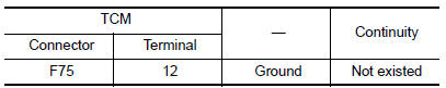
Is the inspection result normal? YES >> GO TO 2.
NO >> Repair or replace malfunctioning part.
2.CHECK CVT UNIT TERMINAL CODE ASSEMBLY
Check continuity between CVT unit connector terminal and ground.
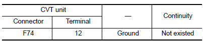
Is the inspection result normal? YES >> GO TO 3.
NO >> There is a malfunction of the CVT unit terminal code assembly. Replace the transaxle assembly.
Refer to TM-220, "Removal and Installation".
3.CHECK CVT FLUID TEMPERATURE SENSOR
Check resistance between CVT unit connector terminals.
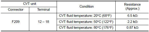
Is the inspection result normal? YES >> INSPECTION END
NO >> There is a malfunction of the CVT fluid temperature sensor. Replace the transaxle assembly.
Refer to TM-220, "Removal and Installation".
 P0711 transmission fluid temperature sensor A
DTC Description
DTC DETECTION LOGIC
DTC
CONSULT screen terms
(Trouble diagnosis content)
DTC detection condition
P0711
FLUID TEMP SENSOR A
(Transmission Fluid Temperat ...
 P0713 transmission fluid temperature sensor A
DTC Description
DTC DETECTION LOGIC
DTC
CONSULT screen terms
(Trouble diagnosis content)
DTC detection condition
P0713
FLUID TEMP SENSOR A
(Transmission Fluid Temperat ...
Other materials:
ECU diagnosis information
A/C AUTO AMP.
Reference Value
VALUES ON THE DIAGNOSIS TOOL
TERMINAL LAYOUT
PHYSICAL VALUES
DTC Inspection Priority Chart
If some DTCs are displayed at the same time, perform inspections one by one
based on the following priority
chart.
Priority
Det ...
Wiring diagram
HEADLAMP
Wiring Diagram
DAYTIME LIGHT SYSTEM
Wiring Diagram
AUTO LIGHT SYSTEM
Wiring Diagram
FRONT FOG LAMP SYSTEM
Wiring Diagram
TURN SIGNAL AND HAZARD WARNING LAMP SYSTEM
Wiring Diagr ...
P0711 transmission fluid temperature sensor A
DTC Description
DTC DETECTION LOGIC
DTC
CONSULT screen terms
(Trouble diagnosis content)
DTC detection condition
P0711
FLUID TEMP SENSOR A
(Transmission Fluid Temperature Sensor A
Circuit Range/Performance)
When any of 1 or 2 is satisfied:
Under the followi ...
