Nissan Rogue Service Manual: Instrument panel assembly
Exploded View
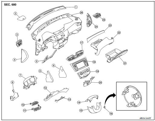
- Defroster grille
- Center speaker grille (if equipped)
- Side ventilator grille (LH)
- Instrument side finisher (LH)
- Knee protector
- Instrument finisher A
- Cluster lid A
- Instrument finisher B (without pushbutton ignition)
- Instrument finisher B (with pushbutton ignition)
- Upper switch carrier
- Lower switch carrier
- Instrument lower panel LH
- Data link cover
- Steering column upper cover
- Steering column lower cover
- Steering lock escutcheon
- Center ventilator grille
- Audio unit (DISPLAY AUDIO) / AV control unit (NAVIGATION WITHOUT BOSE) (NAVIGATION WITH BOSE)
- A/C switch assembly (AUTOMATIC AIR CONDITONING) / front air control (MANUAL AIR CONDITIONING)
- Cluster lid C
- Glove box assembly
- Glove box housing
- Instrument finisher E
- Instrument side finisher (RH)
- Side ventilator grille (RH)
- Instrument panel
INSTRUMENT PANEL ASSEMBLY
INSTRUMENT PANEL ASSEMBLY : Removal and Installation
CAUTION:
- Be careful not to scratch instrument panel pad and other parts.
- Whenever a suitable tool is used, always wrap a cloth around the end of the tool to protect components from damage.
- Before servicing, turn ignition switch OFF, disconnect both battery terminals then wait at least three minutes.
REMOVAL
- Disconnect the negative and positive battery terminals, then wait at least three minutes. Refer to PG-75, "Removal and Installation (Battery)".
- Remove dash side finishers (LH/RH). Refer to INT-24, "DASH SIDE FINISHER : Removal and Installation".
- Remove front pillar finishers (LH/RH). Refer to INT-20, "FRONT PILLAR FINISHER : Removal and Installation".
- Remove combination switch. Refer to EXL-124, "Removal and Installation".
- Remove center console assembly. Refer to IP-18, "Removal and Installation".
- Remove combination meter. Refer to MWI-82, "Removal and Installation".
- Remove audio unit (DISPLAY AUDIO). Refer to AV-64, "Removal and Installation".
- Remove AV control unit. Refer to AV-209, "Removal and Installation" (NAVIGATION WITHOUT BOSE) or AV-376, "Removal and Installation" (NAVIGATION WITH BOSE).
- Remove instrument finisher A. Refer to IP-15, "INSTRUMENT FINISHER A : Removal and Installation".
- Remove instrument finisher B. Refer to IP-16, "INSTRUMENT FINISHER B : Removal and Installation".
- Remove instrument finisher E. Refer to IP-16, "INSTRUMENT FINISHER E : Removal and Installation".
- Remove glove box assembly and housing. Refer to IP-23, "Removal and Installation".
- Remove instrument panel assembly screws.
- Disconnect the harness connectors from the instrument panel assembly and remove.
INSTALLATION
Installation is in the reverse order of removal.
- If replacing the instrument panel, transfer all the necessary parts to the new instrument panel.
INSTRUMENT FINISHER A
INSTRUMENT FINISHER A : Removal and Installation
REMOVAL
- Remove side ventilator grille (LH). Refer to VTL-13, "SIDE VENTILATOR GRILLE : Removal and Installation".
- Remove instrument lower panel LH. Refer to IP-22, "Removal and Installation".
- Release the instrument finisher A clips and pawls using a suitable tool.
 : Pawl
 : Metal clip
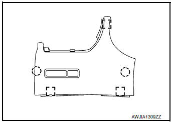
- Disconnect the harness connector from instrument finisher A and remove.
INSTALLATION
Installation is in the reverse order of removal.
INSTRUMENT FINISHER B
INSTRUMENT FINISHER B : Removal and Installation
REMOVAL
- Remove front air control or A/C switch assembly. Refer to HAC-181, "Removal and Installation" (MANUAL AIR CONDITIONING) or HAC-102, "Removal and Installation" (AUTOMATIC AIR CONDITIONING).
- Release the instrument finisher B clips and pawls using a suitable tool.
 : Pawl
 : Metal clip
- Disconnect the harness connector (if equipped) and remove instrument finisher B.
INSTALLATION
Installation is in the reverse order of removal.
INSTRUMENT FINISHER E
INSTRUMENT FINISHER E : Removal and Installation
REMOVAL
- Remove side ventilator grille (RH). Refer to VTL-13, "SIDE VENTILATOR GRILLE : Removal and Installation".
- Release the clips and pawls using a suitable tool and remove instrument finisher E.
Pawl
: Metal clip
INSTALLATION
Installation is in the reverse order of removal

 Steering column covers
Removal and Installation
REMOVAL
Release gap hider (1) pawls from the steering column upper
cover (2).
: Pawl
Remove steering column cover screws (A)
NOTE:
Rotate steering w ...
Other materials:
Car phone or CB radio
When installing a CB, ham radio or car phone in
your vehicle, be sure to observe the following
precautions; otherwise, the new equipment may
adversely affect the engine control system and
other electronic parts.
WARNING
A cellular phone should not be used for
any purpose wh ...
Oil
Description
MAINTENANCE OF OIL LEVEL
The compressor oil is circulating in the system together with the
refrigerant. It is necessary to fill compressor
with oil when replacing A/C system parts or when a large amount of refrigerant
leak is detected. It is important
to always maintain oil level ...
U0141 lost communication (BCM A)
DTC Description
DTC DETECTION LOGIC
DTC
CONSULT screen terms
(Trouble diagnosis content)
DTC detection condition
U0141
LOST COMM (BCM A)
(Lost Communication With Body Control Module
A)
When the ignition switch is turned ON, TCM continues no reception of
the ...
