Nissan Rogue Owners Manual: Head restraints/Headrests
| WARNING Head restraints/headrests supplement the other vehicle safety systems. They may provide additional protection against injury in certain rear end collisions. Adjustable head restraints/headrests must be adjusted properly, as specified in this section. Check the adjustment after someone else uses the seat. Do not attach anything to the head restraint/headrest stalks or remove the head restraint/headrest. Do not use the seat if the head restraint/headrest has been removed. If the head restraint/headrest was removed, reinstall and properly adjust the head restraint/headrest before an occupant uses the seating position. Failure to follow these instructions can reduce the effectiveness of the head restraints/headrests. This may increase the risk of serious injury or death in a collision. |
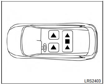
2nd row seating
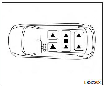
3rd row seating (if so equipped)
The illustration shows the seating positions equipped with head restraints/headrests.
 Indicates the seating position is
equipped with
a head restraint.
Indicates the seating position is
equipped with
a head restraint.
 Indicates the seating position is
equipped with
a headrest.
Indicates the seating position is
equipped with
a headrest.
+ Indicates the seating position is not equipped with a head restraint or headrest (if applicable).
- Your vehicle is equipped with a head restraint/headrest that may be integrated, adjustable or non-adjustable.
- Adjustable head restraints/headrests have multiple notches along the stalk(s) to lock them in a desired adjustment position.
- The non-adjustable head restraints/headrests have a single locking notch to secure them to the seat frame.
- Proper Adjustment:
- For the adjustable type, align the head restraint/headrest so the center of your ear is approximately level with the center of the head restraint/headrest.
- If your ear position is still higher than the recommended alignment, place the head restraint/headrest at the highest position.
- If the head restraint/headrest has been removed, ensure that it is reinstalled and locked in place before riding in that designated seating position.
Adjustable head restraint/headrest components
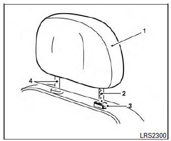
Adjustable head restraint/headrest components
- Removable head restraint/headrest
- Multiple notches
- Lock knob
- Stalks
Non-adjustable head restraint/headrest components
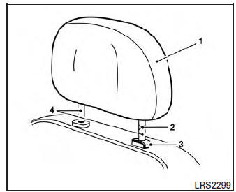
Non-adjustable head restraint/headrest components
- Removable head restraint/headrest
- Single notch
- Lock knob
- Stalks
Remove
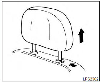
Remove
Use the following procedure to remove the head restraint/headrest:
- Pull the head restraint/headrest up to the highest position.
- Push and hold the lock knob.
- Remove the head restraint/headrest from the seat.
- Store the head restraint/headrest properly in a secure place so it is not loose in the vehicle.
- Reinstall and properly adjust the head restraint/headrest before an occupant uses the seating position.
Install
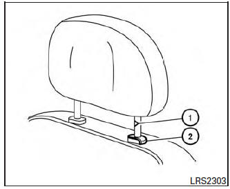
Install
- Align the head restraint/headrest stalks with the holes in the seat. Make sure that the head restraint/headrest is facing the correct direction. The stalk with the notch (notches) 1 must be installed in the hole with the lock knob 2 .
- Push and hold the lock knob and push the head restraint/headrest down.
- Properly adjust the head restraint/headrest before an occupant uses the seating position.
 Flexible seating
WARNING
Never allow anyone to ride in the cargo
area or on the rear seats when they are
in the fold-down position. In a collision,
people riding in these areas without
...
 Adjust
For adjustable head restraint/headrest
Adjust the head restraint/headrest so the center
is level with the center of your ears. If your ear
position is still higher than the recommended
alignment ...
Other materials:
Input speed sensor
Exploded View
Input speed sensor
O-ring
Transaxle assembly
: Always replace after every
disassembly.
: N·m (kg-m, in-lb)
: Apply CVT fluid
Removal and Installation
REMOVAL
Remove battery tray. Refer to TM-207, "Removal and Installation".
Remove the ...
Removal and installation
FRONT AIR CONTROL
Removal and Installation
REMOVAL
Release the front air control clips and pawls using a suitable
tool.
: Metal clip
: Pawl
Disconnect the harness connector from the front air control (1)
and remove.
INSTALLATION
Installation is in the reverse order of ...
Symptom diagnosis
MULTI AV SYSTEM
Symptom Table
RELATED TO AUDIO
RELATED TO HANDS-FREE PHONE
Before performing diagnosis, confirm that the cellular phone being
used by the customer is compatible with
the vehicle.
It is possible that a malfunction is occurring due to a version ...
