Nissan Rogue Service Manual: DTC/circuit diagnosis
U1000 CAN COMM CIRCUIT
Description
Refer to LAN-8, "System Description".
DTC Logic
DTC DETECTION LOGIC
|
CONSULT Display |
DTC Detection Condition |
Possible Cause |
| CAN COMM CIRCUIT [U1000] | When IPDM E/R cannot communicate with CAN communication signal continuously for 2 seconds or more. | In CAN communication system, any item (or items) of
the following listed below is malfunctioning:
|
Diagnosis Procedure
1. PERFORM SELF DIAGNOSTIC RESULT
- Turn ignition switch ON and wait for 2 second or more.
- Check “SELF-DIAG RESULTS” of “IPDM E/R”.
Is “CAN COMM CIRCUIT” displayed? YES >> Refer to LAN-17, "Trouble Diagnosis Flow Chart".
NO >> Refer to GI-41, "Intermittent Incident".
B120E IPDM E/R
DTC Logic
DTC DETECTION LOGIC
|
CONSULT Display |
DTC Detection Condition |
Possible Cause |
| USM ECU Not configured [B120E] | The IPDM E/R detects 0V for greater than 2 seconds.
ECU internal failure. |
IPDM E/R |
DTC CONFIRMATION PROCEDURE
1.PERFORM DTC CONFIRMATION
- Turn ignition switch ON.
- Turn ignition switch OFF and wait 1 second or more.
- Turn ignition switch ON.
- Perform “Self Diagnostic Result” of “IPDM E/R” using CONSULT.
Is DTC B120E displayed? YES >> Refer to PCS-32, "Diagnosis Procedure".
NO >> Inspection End.
Diagnosis Procedure
1. PERFORM SELF DIAGNOSTIC RESULT
Perform “Self Diagnostic Result” of “IPDM E/R” using CONSULT.
Is display history of DTC B120E CRNT? YES >> Replace IPDM E/R. Refer to PCS-35, "Removal and Installation".
NO >> Refer to GI-41, "Intermittent Incident".
B20DD IGNITION RELAY ON CIRCUIT
DTC Logic
DTC DETECTION LOGIC
|
CONSULT Display |
DTC Detection Condition |
Possible Cause |
| IGN RELAY ON [B20DD] | The ignition relay ON is detected for 1 second at ignition switch OFF (CPU monitors the status at the contact and excitation coil circuits of the ignition relay inside it | IPDM E/R |
DTC CONFIRMATION PROCEDURE
1.PERFORM DTC CONFIRMATION
- Turn ignition switch ON.
- Turn ignition switch OFF and wait 1 second or more.
- Turn ignition switch ON.
- Perform “Self Diagnostic Result” of “IPDM E/R” using CONSULT.
Is DTC B20DD displayed? YES >> Refer to PCS-32, "Diagnosis Procedure".
NO >> Inspection End.
Diagnosis Procedure
1. PERFORM SELF DIAGNOSTIC RESULT
Perform “Self Diagnostic Result” of “IPDM E/R” using CONSULT.
Is display history of DTC B20DD CRNT? YES >> Replace IPDM E/R. Refer to PCS-35, "Removal and Installation".
NO >> Refer to GI-41, "Intermittent Incident".
B20DE IGNITION RELAY OFF CIRCUIT
DTC Logic
DTC DETECTION LOGIC
|
CONSULT Display |
DTC Detection Condition |
Possible Cause |
| IGN RELAY OFF [B20DE] | The ignition relay OFF is detected for 1 second at ignition switch ON (CPU monitors the status at the contact and excitation coil circuits of the ignition relay inside it). | IPDM E/R |
DTC CONFIRMATION PROCEDURE
1.PERFORM DTC CONFIRMATION
- Turn ignition switch ON.
- Turn ignition switch OFF and wait 1 second or more.
- Turn ignition switch ON.
- Perform “Self Diagnostic Result” of “IPDM E/R” using CONSULT.
Is DTC B20DE displayed? YES >> Refer to PCS-33, "Diagnosis Procedure".
NO >> Inspection End.
Diagnosis Procedure
1. PERFORM SELF DIAGNOSTIC RESULT
Perform “Self Diagnostic Result” of “IPDM E/R” using CONSULT.
Is display history of DTC B20DE CRNT? YES >> Replace IPDM E/R. Refer to PCS-35, "Removal and Installation".
NO >> Refer to GI-41, "Intermittent Incident".
POWER SUPPLY AND GROUND CIRCUIT
Diagnosis Procedure
Regarding Wiring Diagram information, refer to PCS-24, "Wiring Diagram".
1. CHECK FUSE AND FUSIBLE LINKS
Check that the following IPDM E/R fuse or fusible links are not blown.
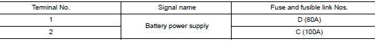
Is the fuse blown? YES >> Replace the blown fuse or fusible link after repairing the affected circuit.
NO >> GO TO 2.
2. CHECK BATTERY POWER SUPPLY CIRCUIT
- Disconnect IPDM E/R connector E118.
- Check voltage between IPDM E/R connector E118 and ground.
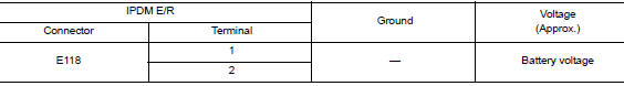
Is the inspection result normal? YES >> GO TO 3.
NO >> Repair or replace harness or connectors.
3. CHECK GROUND CIRCUIT
- Disconnect IPDM E/R connectors E119, E120 and E121.
- Check continuity between IPDM E/R connectors and ground.
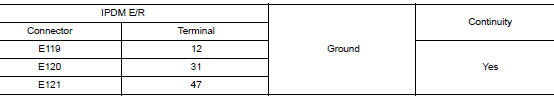
Is the inspection result normal? YES >> Inspection End.
NO >> Repair or replace harness or connectors.
 Wiring diagram
IPDM E/R (INTELLIGENT POWER DISTRIBUTION MODULE ENGINE
ROOM)
Wiring Diagram
...
 Removal and installation
IPDM E/R (INTELLIGENT POWER DISTRIBUTION MODULE ENGINE
ROOM)
Exploded View
IPDM E/R cover
IPDM E/R
IPDM E/R case
IPDM E/R harness cover A
IPDM E/R harness cover B
Front
Remo ...
Other materials:
Both doors mirror defogger don’t operate but rear window defogger operates
Diagnosis Procedure
Regarding Wiring Diagram information, refer to DEF-12, "Wiring Diagram".
1. CHECK DOOR MIRROR DEFOGGER FUSE
Check if the following fuse in fuse block (J/B) is blown.
Is the inspection result normal?
YES >> GO TO 2.
NO >> Replace the blown fuse af ...
Inspection and adjustment
ADDITIONAL SERVICE WHEN REPLACING CONTROL UNIT
ADDITIONAL SERVICE WHEN REPLACING CONTROL UNIT : Description
When replacing the occupant classification system control unit, perform
zero point reset procedure. Refer to
SRC-42, "ZERO POINT RESET : Special Repair Requirement".
When ...
Rear window wiper and washer switch
WARNINGIn freezing temperatures the washer solution
may freeze on the window and obscure
your vision. Warm the rear window
with the defroster before you wash the
rear window.
CAUTION
Do not operate the washer continuously
for more than 30 seconds ...
