Nissan Rogue Service Manual: Drive belts
Exploded view
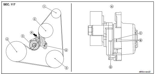
- Generator pulley
- Water pump pulley
- Drive belt auto-tensioner
- Crankshaft pulley
- A/C compressor pulley
- Drive belt retainer boss
- View A
- New drive belt range
- Possible use range
- Indicator (notch)
Checking
WARNING: Inspect the drive belt only when the engine is stopped.
- Visually check entire drive belt for wear, damage or cracks.
- Check that the drive belt auto-tensioner indicator is within the possible use range.
NOTE:
- When new drive belt is installed, the drive belt auto-tensioner indicator should be within the new drive belt range.
- Check the drive belt auto-tensioner indicator when the engine is cold.
- If the drive belt auto-tensioner indicator is out of the possible use range or belt is damaged, replace drive belt.
Tension adjustment
Belt tension is not manually adjustable. It is automatically adjusted by the drive belt auto-tensioner.
Removal and installation
REMOVAL
- Remove wheel and tire (RH) using a power tool.
- Remove engine under cover. Refer to EXT-37, "ENGINE UNDER COVER : Removal and Installation"
- Remove fender protector side cover. Refer to EXT-28, "FENDER PROTECTOR : Exploded View".
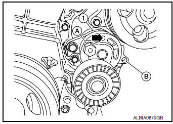
- Securely hold the hexagonal part (A) of drive belt auto-tensioner (1) using suitable tool, and move in the direction of arrow (loosening direction of tensioner).
- Insert a rod approximately 6 mm (0.24 in) in diameter through the rear of the drive belt auto-tensioner into retaining boss (B) to lock drive belt auto-tensioner pulley.
WARNING: Avoid placing hand in a location where pinching may occur if the holding tool accidentally comes off.
NOTE: Leave drive belt auto-tensioner pulley arm locked until drive belt is installed again.
- Loosen drive belt from drive belt auto-tensioner and then remove it from the other pulleys.
- Installation of remaining components is in the reverse order of removal.
INSTALLATION
Installation is in the reverse order of removal.
- Install the drive belt onto all of the pulleys except for the drive belt auto-tensioner. Then install the drive belt onto drive belt auto-tensioner last.
CAUTION:
- Confirm belts are completely set on the pulleys.
- Check for engine oil and engine coolant. Be sure they are not adhered to the drive belt and each pulley groove.
- Release the drive belt auto-tensioner and apply tension to drive belt.
WARNING: Avoid placing hand in a location where pinching may occur if the holding tool accidentally comes off.
- Turn crankshaft pulley clockwise several times to equalize tension between each pulley.
- Confirm the indicator is within the possible use range. Refer to EM-13, "Checking"
- Install wheel and tire (RH). Refer to WT-57, "Adjustment".
Removal and installation of drive belt auto-tensioner
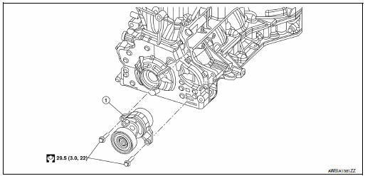
- Drive belt auto-tensioner
REMOVAL
CAUTION: The complete drive belt auto-tensioner must be replaced as a unit, including the pulley.
- Remove the drive belt. Refer to EM-13, "Removal and Installation".
- Remove the drive belt auto-tensioner.
INSTALLATION
Installation is in the reverse order of removal.
CAUTION: Install the drive belt auto-tensioner carefully so not to damage the water pump pulley.

 Air cleaner filter
Exploded view
Mass air flow sensor
Air cleaner filter
Air cleaner case (lower)
Air duct assembly
Grommet
Resonator bracket (front)
Resonator bracket (rear)
...
Other materials:
Periodic maintenance
IDLE SPEED
Inspection
1.CHECK IDLE SPEED
With CONSULT
Check idle speed in “DATA MONITOR” mode of “ENGINE” using CONSULT.
With GST
Check idle speed with Service $01 of GST.
>> INSPECTION END
IGNITION TIMING
Inspection
1.CHECK IGNITION TIMING
Attach timing light (A) to th ...
P2014, P2016, P2017, P2018 intake manifold runner control
valve position sensor
DTC Description
DTC DETECTION LOGIC
DTC No.
CONSULT screen terms
(Trouble diagnosis content)
DTC detecting condition
P2014
IN/MANIFOLD RUNNER POS SEN B1
(Intake manifold runner position sensor/
switch circuit bank 1)
An excessively low voltage from the sensor i ...
Fuses
Two types of fuses are used. Type A is used in
the fuse boxes in the engine compartment. Type
B is used in the passenger compartment fuse
box.
Type A fuses are provided as spare fuses. They
are stored in the passenger compartment fuse
box.
Type A fuses can be installed in the engine
co ...
