Nissan Rogue Service Manual: Basic inspection
DIAGNOSIS AND REPAIR WORKFLOW
Work Flow
OVERALL SEQUENCE
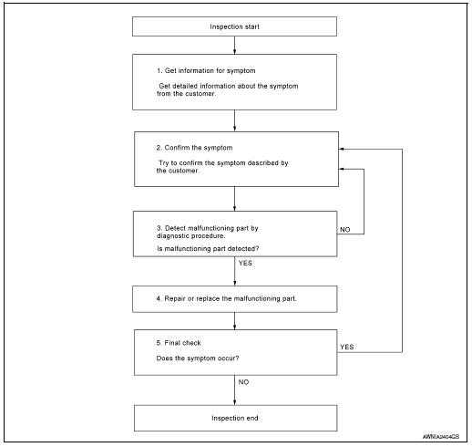
DETAILED FLOW
1.GET INFORMATION FOR SYMPTOM
Get detailed information from the customer about the symptom (the condition and the environment when the incident/malfunction occurred).
>> GO TO 2.
2.CONFIRM THE SYMPTOM
Try to confirm the symptom described by the customer. Verify relation between the symptom and the condition when the symptom is detected. Refer to AV-59, "Symptom Table".
>> GO TO 3.
3.DETECT MALFUNCTIONING PART BY DIAGNOSTIC PROCEDURE
Inspect according to Diagnostic Procedure of the system.
Is malfunctioning part detected? YES >> GO TO 4.
NO >> GO TO 2.
4.REPAIR OR REPLACE THE MALFUNCTIONING PART
- Repair or replace the malfunctioning part.
- Reconnect parts or connectors disconnected during Diagnostic Procedure.
>> GO TO 5.
5.FINAL CHECK
Refer to confirmed symptom in step 2, and make sure that the symptom is not detected.
Was the repair confirmed? YES >> Inspection End.
NO >> GO TO 2.
 Wiring diagram
DISPLAY AUDIO
Wiring Diagram
...
 DTC/circuit diagnosis
POWER SUPPLY AND GROUND CIRCUIT
AUDIO UNIT
AUDIO UNIT : Diagnosis Procedure
Regarding Wiring Diagram information, refer to AV-27, "Wiring Diagram".
1.CHECK FUSE
Check that the following ...
Other materials:
Rear wiper and washer system
Wiring Diagram
...
Cluster lid C
Exploded View
Audio unit (AUDIO WITHOUT BOSE) /
AV control unit (AUDIO WITH BOSE)
(NAVIGATION WITH BOSE)
A/C switch assembly (AUTOMATIC
AIR CONDITIONING) / front air control
(MANUAL AIR CONDITIONING)
Cluster lid C
Removal and Installation
REMOVAL
Release ...
Plug
Description
Replace the O-ring if oil leakage or exudes from the plug.
Exploded View
Transaxle assembly
O-ring
Plug
: Always replace after every
disassembly.
: N·m (kg-m, ft-lb)
: Apply CVT fluid
Removal and Installation
REMOVAL
Partially remove front fender prote ...
