Nissan Rogue Service Manual: Air cleaner and air duct
Exploded View
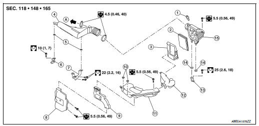
- Mass air flow sensor
- Air cleaner filter
- Air cleaner case (lower)
- Air duct assembly
- Grommet
- Resonator bracket (front)
- Resonator bracket (rear)
- Resonator
- Air duct
- Mounting clip
- Air duct assembly
- Air cleaner case duct
- Air cleaner bracket
- Grommet
- Air cleaner case (upper)
- To Electric throttle control actuator
Removal and Installation
REMOVAL
NOTE: Mass air flow sensor is removable under the car-mounted condition.
- Remove cowl top extension. Refer to EXT-25, "Removal and Installation".
- Remove air cleaner filter. Refer to EM-16, "Removal and Installation".
- Remove air duct assembly from air cleaner case (lower).
- Remove air cleaner case (lower).
- Disconnect harness connector from mass air flow sensor.
- Remove air cleaner case (upper).
- Remove mass air flow sensor from air cleaner case (upper) (if necessary).
- Separate air cleaner case duct from air cleaner case (lower) and air duct assembly.
- Remove air duct from air duct assembly and resonator.
- Remove resonator.
INSTALLATION
Installation is in the reverse order of removal.
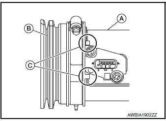
- Align mating marks (C) of air duct assembly (B) with air cleaner case (upper) (A) as shown.
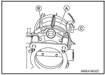
- Align mating marks (C) of air duct assembly (A) with electric throttle control actuator (B) as shown.
Inspection
INSPECTION AFTER REMOVAL
Inspect air duct and resonator assembly for cracks or tears.
- If anything found, replace air duct and resonator assembly.

 Intake manifold
Exploded View
Intake manifold
Intake manifold gasket
Electirc throttle control actuator O-ring
Electric throttle control actuator
Removal and Installation
REMOVAL ...
Other materials:
Air bags, seat belts and child restraints
Supplemental front-impact air bags
Occupant classification sensor (weight sensor)
Seat belts
Head restraints/headrests
Roof-mounted curtain side-impact and rollover supplemental air bag
2nd row center position top tether strap (located on ceiling) ...
Lifting point
Special service tool
The actual shapes of Kent-Moore tools may differ from those of special
service tools illustrated here.
Tool number
(Kent-Moore No.)
Tool name
Description
LM4086-0200
( - )
Board on attachment
LM4519-0000
( - )
Safety stan ...
Periodic maintenance
REAR WHEEL HUB AND HOUSING
Inspection
INSPECTION
Make sure the conditions (looseness, back lash) of each component and
component conditions (wear, damage)
are normal.
WHEEL HUB AND BEARING INSPECTION
Move wheel hub and bearing in the axial direction by hand. Make
sure there is no ...
