Nissan Rogue Service Manual: Stall test
Work Procedure
INSPECTION
- Check the engine oil level. Replenish if necessary. Refer to LU-7, "Inspection".
- Check for leak of the CVT fluid. Refer to TM-190, "Inspection".
- Drive for about 10 minutes to warm up the vehicle so that the CVT fluid temperature is 50 to 80°C (122 to 176°F).
- Be sure to apply the parking brake and block the tires.
- Start the engine, depress the brake pedal and put the selector lever to the D position.
- While depressing the brake pedal, depress the accelerator pedal gradually.
- Read the stall speed quickly. Then, release your foot from the accelerator pedal quickly.
CAUTION: Do not depress the accelerator pedal for 5 seconds or more during the test.
Stall speed : Refer to TM-226, "Stall Speed".
- Place the selector lever in the N position.
- Cool the CVT fluid.
CAUTION: Run the engine with the idle speed for at least 1 minute.
- Put the selector lever to the R position and perform Step 6 to Step 9 again.
NARROWING-DOWN MALFUNCTIONING PARTS
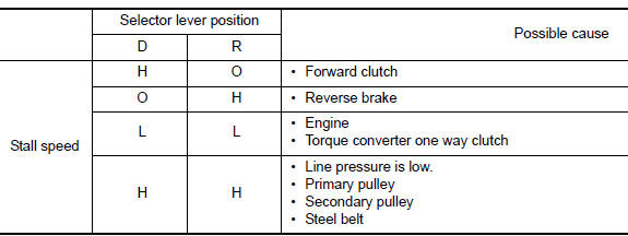
O: Within the stall speed standard value.
H: Stall speed is higher than the standard value.
L: Stall speed is lower than the standard value.
 CVT fluid cooler system
Cleaning
Whenever an automatic transaxle is repaired, overhauled, or replaced, the CVT
fluid cooler mounted in the
radiator must be inspected and cleaned.
Metal debris and friction material, if ...
 CVT position
Inspection
Turn ON the ignition switch with the shift selector at the “P” position.
Press the shift selector button with the brake pedal depressed,
and confirm that the shift select ...
Other materials:
Glove box lamp
Bulb Replacement
WARNING:
Do not touch the glass surface of a bulb while it is lit or right after being
turned OFF to prevent burns.
CAUTION:
Do not touch the glass of bulb directly by hand. Keep grease
and other oily substances away from
bulb surface.
Do not leave bulb ...
Power generation voltage variable control system operation
inspection
Diagnosis Procedure
Regarding Wiring Diagram information. Refer to CHG-7, "Wiring Diagram".
CAUTION:
When performing this inspection, always use a charged battery that has completed
the battery inspection.
(When the charging rate of the battery is low, the response speed of the vol ...
P0075 intake valve timing control
DTC Description
DTC DETECTION LOGIC
DTC No.
CONSULT screen terms
(Trouble diagnosis content)
DTC detecting condition
P0075
INT/V TIM V/CIR-B1
(Intake valve control solenoid circuit bank 1)
ECM detects an abnormal voltage in the intake valve timing
co ...
