Nissan Rogue Service Manual: P2004 intake manifold runner control valve
DTC Description
DTC DETECTION LOGIC
| DTC No. | CONSULT screen terms (Trouble diagnosis content) | DTC detecting condition |
| P2004 | TUMBLE CONT/V (Intake manifold runner control stuck open bank 1) | The target angle of intake manifold runner control valve controlled by ECM and the input signal from intake manifold runner control valve position sensor is not in the normal range. |
POSSIBLE CAUSE
- Harness or connectors (Intake manifold runner control valve motor circuit is open or shorted.)
- Intake manifold runner control valve motor
- Intake manifold runner control valve is stuck
FAIL-SAFE
- Traveling control mode (Engine output control)
- Device fix mode
DTC CONFIRMATION PROCEDURE
1.PRECONDITIONING
If DTC Confirmation Procedure has been previously conducted, always turn ignition switch OFF and wait at least 10 seconds before conducting the next test.
TESTING CONDITION:
- Before performing the following procedure, confirm that battery voltage is more than 11 V at idle.
- Always perform the test at a temperature above −7¬∞C (19¬∞F)
>> GO TO 2.
2.PERFORM DTC CONFIRMATION PROCEDURE
 With CONSULT
- Turn ignition switch ON.
- Select “DATA MONITOR” mode with CONSULT.
- Make sure that ‚ÄúCOOLAN TEMP/S‚Äù indicates between −7¬∞C (19¬∞F) to
60°C (140°F).
If not, cool engine down or warm engine up until ‚ÄúCOOLAN TEMP/S‚Äù indicates between −7¬∞C (19¬∞F) to 60¬∞C (140¬∞F). Then go to the following steps.
- Fully release accelerator pedal and wait at least 10 seconds.
- Depress accelerator pedal and wait at least 10 seconds.
- Check 1st trip DTC.
 With GST
Following the procedure “With CONSULT” above.
Is 1st trip DTC detected? YES >> Proceed to EC-420, "Diagnosis Procedure".
NO >> INSPECTION END
Diagnosis Procedure
1.CHECK INTAKE MANIFOLD RUNNER CONTROL VALVE MOTOR POWER SUPPLY
- Turn ignition switch ON.
- Check the voltage between ECM harness connector.
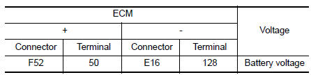
Is the inspection result normal? YES >> GO TO 3.
NO >> GO TO 2.
2.CHECK INTAKE MANIFOLD RUNNER CONTROL VALVE MOTOR POWER SUPPLY CIRCUIT
- Turn ignition switch OFF.
- Disconnect ECM harness connector.
- Disconnect IPDM E/R harness connector.
- Check the continuity between ECM harness connector and IPDM E/R harness connector.
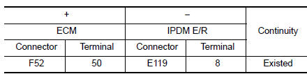
- Also check harness for short to ground.
Is the inspection result normal? YES >> Perform the trouble diagnosis for power supply circuit.
NO >> Repair or replace error-detected parts.
3.CHECK INTAKE MANIFOLD RUNNER CONTROL VALVE MOTOR OUTPUT SIGNAL CIRCUIT
- Disconnect intake manifold runner control valve motor harness connector.
- Check the continuity between intake manifold runner control valve motor harness connector and ECM harness connector.
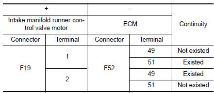
- Also check harness for short to ground and to power.
Is the inspection result normal? YES >> GO TO 4.
NO >> Repair or replace error-detected parts.
4.CHECK INTAKE MANIFOLD RUNNER CONTROL VALVE MOTOR
Check the intake manifold runner control valve motor. Refer to EC-421, "Component Inspection".
Is the inspection result normal? YES >> GO TO 5.
NO >> Replace intake manifold assembly. Refer to EM-26, "Removal and Installation".
5.CHECK INTERMITTENT INCIDENT
Refer to GI-41, "Intermittent Incident".
>> INSPECTION END
Component Inspection
1.CHECK INTAKE MANIFOLD RUNNER CONTROL VALVE
 With CONSULT
- Turn ignition switch ON.
- Select “DATA MONITOR” mode with CONSULT.
- Make sure that ‚ÄúCOOLAN TEMP/S‚Äù indicates between −7¬∞C (19¬∞F) to 60¬∞C
(140°F).
If not, cool engine down or warm engine up until ‚ÄúCOOLAN TEMP/S‚Äù indicates between −7¬∞C (19¬∞F) to 60¬∞C (140¬∞F). Then go to the following steps.
- Fully release accelerator pedal and make sure that “TUMBLE POS SEN” indicates between 2.8 V to 4.1 V.
- Depress accelerator pedal and make sure that “TUMBLE POS SEN” indicates between 0.2 V to 1.4 V.
- Check 1st trip DTC.
 With GST
Following the procedure “With CONSULT” above.
Is 1st trip DTC detected? YES >> Replace intake manifold assembly. Refer to EM-26, "Removal and Installation".
NO >> GO TO 2.
2.CHECK INTAKE MANIFOLD RUNNER CONTROL VALVE MOTOR
- Turn ignition switch OFF.
- Disconnect intake manifold runner control valve motor harness connector.
- Check the resistance between intake manifold runner control valve motor terminals as per the following.
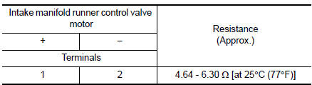
Is the inspection result normal? YES >> INSPECTION END
NO >> Replace intake manifold assembly. Refer to EM-26, "Removal and Installation".
 P1805 brake switch
DTC Description
DTC DETECTION LOGIC
DTC No.
CONSULT screen terms
(Trouble diagnosis content)
DTC detecting condition
P1805
BRAKE SW/CIRCUIT
(BRAKE SW/CIRCUT)
A stop ...
 P2014, P2016, P2017, P2018 intake manifold runner control
valve position sensor
P2014, P2016, P2017, P2018 intake manifold runner control
valve position sensor
DTC Description
DTC DETECTION LOGIC
DTC No.
CONSULT screen terms
(Trouble diagnosis content)
DTC detecting condition
P2014
IN/MANIFOLD RUNNER POS SEN B1
(Intake manifo ...
Other materials:
Operating range
Operating range
The Intelligent Key functions can only be used
when the Intelligent Key is within the specified
operating range.
When the Intelligent Key battery is almost discharged
or strong radio waves are present near
the operating location, the Intelligent Key system’s
operating ...
Periodic maintenance
REAR PROPELLER SHAFT
Inspection
APPEARANCE AND NOISE
Check the propeller shaft tube surface for dents or cracks. If
malfunction is detected, replace propeller shaft
assembly.
If center bearing is noisy or damaged, replace propeller shaft
assembly.
VIBRATION
If vibrati ...
The light reminder warning does not sound
Description
Light reminder warning does not sound even though headlamp is illuminated.
Diagnosis Procedure
1.CHECK COMBINATION METER INPUT SIGNAL
Select the "Data Monitor" for the "METER/M&A" and check the "BUZZER" monitor
value.
Is the inspection result ...
