Nissan Rogue Service Manual: P0011 IVT control
DTC Description
DTC DETECTION LOGIC
| DTC No. | CONSULT screen terms (Trouble diagnosis content) | DTC detecting condition |
| P0011 | INT/V TIM CONT-B1 (″A″ Camshaft position - timing over-advanced or system performance bank 1) | There is a gap between angle of target and phase-control angle degree. |
POSSIBLE CAUSE
- Crankshaft position sensor (POS)
- Camshaft position sensor (PHASE)
- Intake valve control solenoid valve
- Accumulation of debris to the signal pick-up portion of the camshaft
- Timing chain installation
- Foreign matter caught in the oil groove for intake valve timing control
FAIL-SAFE
- Device fix mode
- ECM activates the IVT intermediate lock control solenoid valve to bring the cam sprocket into an intermediate lock condition.
DTC CONFIRMATION PROCEDURE
1.CHECK DTC PRIORITY
If DTC P0011 is displayed with DTC P0075, first perform the trouble diagnosis for DTC P0075.
Is applicable DTC detected? YES >> Perform diagnosis of applicable. Refer to EC-191, "DTC Description".
NO >> GO TO 2.
2.PRECONDITIONING
If DTC Confirmation Procedure has been previously conducted, always perform the following procedure before conducting the next test.
- Turn ignition switch OFF and wait at least 10 seconds.
- Turn ignition switch ON.
- Turn ignition switch OFF and wait at least 10 seconds.
TESTING CONDITION: Before performing the following procedure, confirm that battery voltage is between 11 V and 16 V at idle. >> GO TO 3.
3.PERFORM DTC CONFIRMATION PROCEDURE-1
 With CONSULT
- Turn ignition switch ON and select “DATA MONITOR” mode of “ENGINE” using CONSULT.
- Start engine and warm it up to normal operating temperature.
- Maintain the following conditions for at least 13 consecutive seconds. Hold the accelerator pedal as steady as possible.
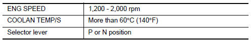
- Stop vehicle with engine running and let engine idle for 13 seconds.
- Check 1st trip DTC.
 With GST
Follow the procedure “With CONSULT” above.
Is 1st trip DTC detected? YES >> Proceed to EC-178, "Diagnosis Procedure".
NO >> GO TO 4.
4.PERFORM DTC CONFIRMATION PROCEDURE-2
With CONSULT
- Maintain the following conditions for at least 20 consecutive seconds.
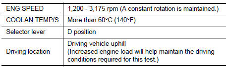
CAUTION: Always drive at a safe speed.
- Check 1st trip DTC.
With GST
Follow the procedure “With CONSULT” above.
Is 1st trip DTC detected? YES >> Proceed to EC-178, "Diagnosis Procedure".
NO >> INSPECTION END
Diagnosis Procedure
1.CHECK DTC PRIORITY
If DTC P0011 is displayed with DTC P0075, first perform the trouble diagnosis for DTC P0075.
Is applicable DTC detected? YES >> Perform diagnosis of applicable. Refer to EC-191, "DTC Description".
NO >> GO TO 2.
2.CHECK OIL PRESSURE WARNING LAMP
- Start engine.
- Check oil pressure warning lamp and confirm it is not illuminated.
Is oil pressure warning lamp illuminated? YES >> Check the engine oil level. Refer to LU-7, "Inspection".
NO >> GO TO 3.
3.CHECK INTAKE VALVE TIMING CONTROL SOLENOID VALVE
Check the intake valve timing control solenoid valve. Refer to EC-179, "Component Inspection".
Is the inspection result normal? YES >> GO TO 4.
NO >> Replace intake valve timing control solenoid valve. Refer to EM-44, "Exploded View"
4.CHECK CRANKSHAFT POSITION SENSOR (POS)
Check the crankshaft position sensor (POS). Refer to EC-297, "Component Inspection (Crankshaft Position sensor)".
Is the inspection result normal?
YES >> GO TO 5.
NO >> Replace crankshaft position sensor (POS). Refer to EM-92, "Exploded View".
5.CHECK CAMSHAFT POSITION SENSOR (PHASE)
Check the camshaft position sensor (PHASE). Refer to EC-300, "Component Inspection (Camshaft position sensor)".
Is the inspection result normal? YES >> GO TO 6.
NO >> Replace camshaft position sensor (PHASE). Refer to EM-64, "Exploded View".
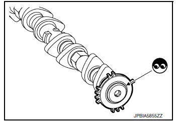
6.CHECK CAMSHAFT (INT)
Check the following.
- Accumulation of debris to the signal plate of camshaft rear end
- Chipping signal plate of camshaft rear end
Is the inspection result normal? YES >> GO TO 7.
NO >> Remove debris and clean the signal plate of camshaft rear end or replace camshaft. Refer to EM-64, "Removal and Installation".
7.CHECK TIMING CHAIN INSTALLATION
Check service records for any recent repairs that may cause timing chain misaligned.
Are there any service records that may cause timing chain misaligned? YES >> Check timing chain installation. Refer to EM-45, "Removal and Installation".
NO >> GO TO 8.
8.CHECK LUBRICATION CIRCUIT
Refer to LU-7, "Inspection", “INSPECTION AFTER INSTALLATION”.
Is the inspection result normal? YES >> GO TO 9.
NO >> Clean lubrication line.
9.CHECK INTERMITTENT INCIDENT
Refer to GI-41, "Intermittent Incident".
>> INSPECTION END
Component Inspection
1.CHECK INTAKE VALVE TIMING CONTROL SOLENOID VALVE-1
- Turn ignition switch OFF.
- Disconnect intake valve timing control solenoid valve harness connector.
- Check resistance between intake valve timing control solenoid valve terminals as per the following.
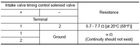
Is the inspection result normal?
YES >> GO TO 2.
NO >> Replace intake valve timing control solenoid valve. Refer to EM-44, "Exploded View".
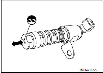
2.CHECK INTAKE VALVE TIMING CONTROL SOLENOID VALVE-2
- Remove intake valve timing control solenoid valve. Refer to EM-44, "Exploded View".
- Provide 12 V DC between intake valve timing control solenoid valve terminals 1 and 2, and then interrupt it. Make sure that the plunger moves as shown in the figure.
CAUTION: Do not apply 12 V DC continuously for 5 seconds or more.
Doing so may result in damage to the coil in intake valve timing control solenoid valve.
NOTE: Always replace O-ring when intake valve timing control solenoid valve is removed.
Is the inspection result normal? YES >> INSPECTION END
NO >> Replace intake valve timing control solenoid valve. Refer to EM-44, "Exploded View".
 U1050, U1051 LIN communication
DTC Description
DTC DETECTION LOGIC
DTC No.
CONSULT screen terms
(Trouble diagnosis content)
DTC detecting condition
U1050
LIN COMMUNICATION
[LIN (Local Interconnect N ...
 P0014 EVT control
DTC Description
DTC DETECTION LOGIC
DTC No.
CONSULT screen terms
(Trouble diagnosis content)
DTC detecting condition
P0014
EXH/V TIM CONT-B1
(″B″ Camshaft ...
Other materials:
Wiring diagram
HEADLAMP
Wiring Diagram
DAYTIME LIGHT SYSTEM
Wiring Diagram
AUTO LIGHT SYSTEM
Wiring Diagram
FRONT FOG LAMP SYSTEM
Wiring Diagram
TURN SIGNAL AND HAZARD WARNING LAMP SYSTEM
Wiring Diagr ...
Brake fluid
Drain and Refill
CAUTION:
Do not spill or splash brake fluid on painted surfaces. Brake
fluid may damage paint. If brake fluid is
splashed on painted areas, wash it away with water immediately.
Prior to repair, turn the ignition switch OFF, disconnect the
ABS actuator and ...
Ignition switch (if so equipped)
WARNING
Never remove or turn the key to the
LOCK position while driving. The steering
wheel will lock (for models with a
steering lock mechanism). This may
cause the driver to lose control of the
vehicle and could result in serious vehicle
damage or personal ...
