Nissan Rogue Service Manual: Front regulator
Exploded View
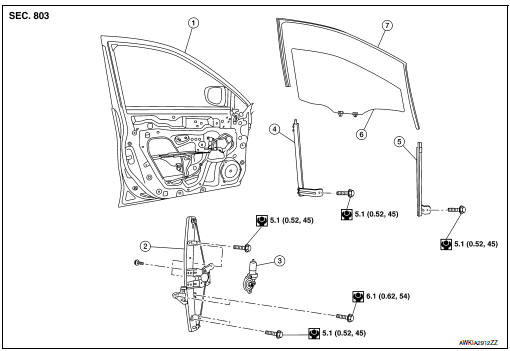
- Front door panel
- Front door regulator
- Front door power window motor
- Front door glass run rear
- Front door glass run front
- Front door glass
- Front door glass rubber run
Removal and Installation
REMOVAL
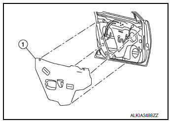
- Remove the front door finisher. Refer to INT-15, "Removal and Installation".
- Partially remove vapor barrier.
- Temporarily reconnect the main power window and door lock/unlock switch (LH door) or power window door lock/unlock switch RH (RH door).
- Operate the power window and door lock/unlock switch (LH door) or front door power window motor and door lock/unlock switch RH (RH door) to raise/lower the front door glass until the front door regulator to front door glass bolts can be seen.
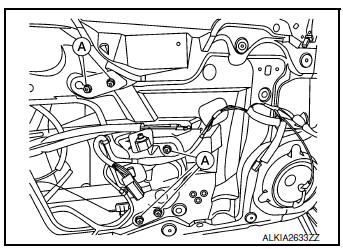
- Raise the front door glass and hold in place using a suitable tool (A).
- Disconnect the harness connector from the front power window motor.
- Remove the bolts (A) and remove the front door glass regulator.
INSPECTION AFTER REMOVAL
Check the front door glass regulator for the following items:
- Wire wear
- Front door glass regulator deformation
- Grease condition for each sliding part
If a malfunction is detected, replace or grease it.
The arrows in the figure show the application points of the suitable multi-purpose grease, if needed.
Inspection and Adjustment
INSTALLATION
Installation is in the reverse order of removal.
CAUTION:
- When the main power window and door lock/unlock switch or front power window and door lock/ unlock switch RH is removed it is necessary to perform the initialization procedure. Refer to PWC- 27, "ADDITIONAL SERVICE WHEN REMOVING BATTERY NEGATIVE TERMINAL : Special Repair Requirement".
- Tighten front door regulator bolts to specification. Refer to GW-16, "Exploded View".
FITTING INSPECTION
- Check that the front door glass is fit securely into the glass run groove.
- Lower the front door glass slightly [approximately 10 to 20 mm (0.39 to 0.79) and check that the clearance to the run is parallel.If the clearance between the glass and sash is not parallel, loosen the front door glass regulator bolts, front door glass run channel bolts, and glass and run rail bolts to correct the glass position.
 Front door glass
Exploded View
Front door
Front regulator
Front power window motor
Front door glass rear run
Front door glass front run
Front door glass
Front door glass rubber run
Remo ...
 Front power window motor
Removal and Installation
REMOVAL
Remove front door glass regulator. Refer to GW-16, "Removal and
Installation".
Remove screws (A) and front power window motor (1) from ...
Other materials:
Over fender
FRONT OVER FENDER
FRONT OVER FENDER : Exploded View
Front fender protector
Front fender
Front over fender molding
Clip
FRONT OVER FENDER : Removal and Installation
REMOVAL
Remove front and rear screw (A).
1: Front over fender
2: Sill molding
: Front
...
Component parts
Component Parts Location
ENGINE ROOM COMPARTMENT
No.
Component
Function
1
IPDM E/R
IPDM E/R control the internal relays and the actuators.
Refer to PCS-5, "RELAY CONTROL SYSTEM : System
Description".
When CAN comm ...
Preparation
Special Service Tool
The actual shape of the tools may differ from those illustrated here.
Tool number
(TechMate No.)
Tool name
Description
—
(165-GR8-1200KIT-NI)
Multitasking battery and electrical diagnostic
station
Testing batteries, starti ...
