Nissan Rogue Service Manual: Encoder circuit
Description
Detects condition of the front power window motor LH operation and transmits to main power window and door lock/unlock switch as pulse signal.
Component Function Check
1.CHECK ENCODER OPERATION
Check front driver side door glass perform AUTO open/close operation normally when main power window and door lock/unlock switch.
Is the inspection result normal? YES >> Encoder operation is OK.
NO >> Refer to PWC-45, "Diagnosis Procedure"
Diagnosis Procedure
Encoder Circuit Check
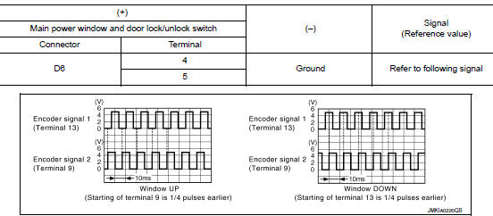
1.CHECK ENCODER OPERATION
- Turn ignition switch ON.
- Check signal between main power window and door lock/unlock switch harness connector and ground with oscilloscope.
Is the inspection result normal? YES >> GO TO 7.
NO >> GO TO 2.
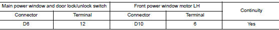
2.CHECK ENCORDER SIGNAL CIRCUIT
- Turn ignition switch OFF.
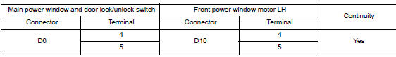
- Disconnect main power window and door lock/unlock switch connector and front power window motor LH connector.
- Check continuity between main power window and door lock/unlock switch harness connector and front power window motor LH harness connector.
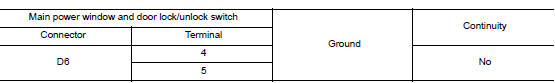
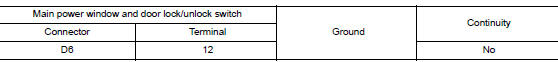
- Check continuity between main power window and door lock/unlock switch harness connector and ground.
Is the inspection result normal? YES >> GO TO 3.
NO >> Repair or replace harness.
3.CHECK ENCORDER POWER SUPPLY CIRCUIT
- Connect main power window and door lock/unlock switch connector.
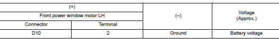
- Turn ignition switch ON.
- Check voltage between front power window motor LH harness connector and ground.
Is the inspection result normal? YES >> GO TO 4.
NO >> GO TO 5.
4.CHECK GROUND CIRCUIT
- Turn ignition switch OFF.
- Check continuity between front power window motor LH harness connector and ground.
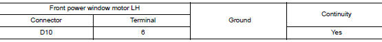
Is the inspection result normal? YES >> GO TO 7.
NO >> GO TO 6.
5.CHECK HARNESS CONTINUITY 1
- Turn ignition switch OFF.
- Check continuity between main power window and door lock/unlock switch harness connector and front power window motor LH harness connector.
- Check continuity between main power window and door lock/unlock switch harness connector and ground.
Is the inspection result normal? YES >> Replace main power window and door lock/unlock switch. Refer to PWC-65, "Removal and Installation".
NO >> Repair or replace harness.
6.CHECK HARNESS CONTINUITY 2
- Disconnect main power window and door lock/unlock switch connector.
- Check continuity between main power window and door lock/unlock switch harness connector and front power window motor LH harness connector.
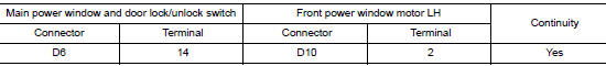
Is the inspection result normal? YES >> Replace main power window and door lock/unlock switch. Refer to PWC-65, "Removal and Installation".
NO >> Repair or replace harness.
7.CHECK INTERMITTENT INCIDENT
Refer to GI-41, "Intermittent Incident".
>> Inspection End.
 Power window motor
DRIVER SIDE
DRIVER SIDE : Description
Door glass moves UP/DOWN by receiving the signal from main power window and
door lock/unlock switch.
DRIVER SIDE : Component Function Check
1. CHECK FRONT P ...
 Power window relay
Description
Power is supplied to the main power window and door lock/unlock with BCM
control.
Component Function Check
1. CHECK POWER WINDOW RELAY POWER SUPPLY CIRCUIT
Check that an operation no ...
Other materials:
P1212 TCS communication line
Description
This CAN communication line is used to control the smooth engine operation
during the TCS operation. Pulse
signals are exchanged between ECM and “ABS actuator and electric unit (control
unit)”.
Be sure to erase the malfunction information such as DTC not only for “ABS
ac ...
Preparation
Special Service Tools
The actual shape of the tools may differ from those illustrated here.
Tool number
(TechMate No.)
Tool name
Description
—
(J-46534)
Trim Tool Set
Removing trim components
...
P1572 brake pedal position switch
DTC Description
DTC DETECTION LOGIC
NOTE:
This self-diagnosis has the one trip detection logic. When malfunction A is
detected, DTC is not stored
in ECM memory. And in that case, 1st trip DTC and 1st trip freeze frame data are
displayed. 1st trip
DTC is erased when ignition switch OFF. And ...
