Nissan Rogue Service Manual: DTC/circuit diagnosis
POWER SUPPLY AND GROUND CIRCUIT BCM (BODY CONTROL SYSTEM) (WITH INTELLIGENT KEY SYSTEM)
BCM (BODY CONTROL SYSTEM) (WITH INTELLIGENT KEY SYSTEM) : Diagnosis Procedure
Regarding Wiring Diagram information, refer to BCS-50, "Wiring Diagram".
1. CHECK FUSE
Check that the following fuse is not blown.

Is the fuse blown? YES >> Replace the blown fuse after repairing the affected circuit.
NO >> GO TO 2.
2. CHECK POWER SUPPLY CIRCUIT
- Disconnect BCM connector M20.
- Check voltage between BCM connector M20 and ground.
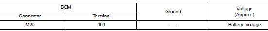
Is the inspection result normal? YES >> GO TO 3.
NO >> Repair or replace harness or connectors.
3. CHECK GROUND CIRCUIT
Check continuity between BCM connector M20 and ground.
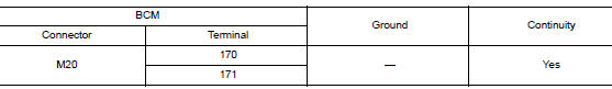
Is the inspection result normal? YES >> Inspection End.
NO >> Repair or replace harness or connectors.
BCM (BODY CONTROL SYSTEM) (WITHOUT INTELLIGENT KEY SYSTEM)
BCM (BODY CONTROL SYSTEM) (WITHOUT INTELLIGENT KEY SYSTEM) : Diagnosis Procedure
Regarding Wiring Diagram information, refer to BCS-110, "Wiring Diagram".
1. CHECK FUSE
Check that the following fuse is not blown.

Is the fuse blown? YES >> Replace the blown fuse after repairing the affected circuit.
NO >> GO TO 2.
2. CHECK POWER SUPPLY CIRCUIT
- Disconnect BCM connector M20.
- Check voltage between BCM connector M20 and ground.
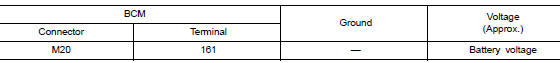
Is the inspection result normal? YES >> GO TO 3.
NO >> Repair or replace harness or connectors.
3. CHECK GROUND CIRCUIT
Check continuity between BCM connector M20 and ground.
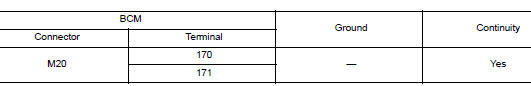
Is the inspection result normal? YES >> Inspection End.
NO >> Repair or replace harness or connectors.
OPTICAL SENSOR
Component Function Check
1.CHECK OPTICAL SENSOR SIGNAL BY CONSULT
 CONSULT DATA MONITOR
- Turn power switch ON.
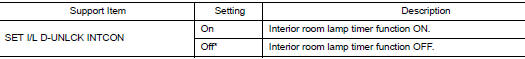
- Select ŌĆ£OPTICAL SENSORŌĆØ of BCM (HEADLAMP) data monitor item.
- Turn lighting switch AUTO.
- With the optical sensor illuminating, check the monitor status.
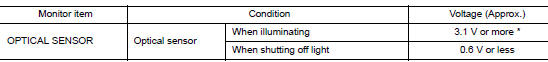
*: Illuminates the optical sensor. The value may be less than the standard value if brightness is weak.
Is the inspection result normal? YES >> Optical sensor is normal.
NO >> Refer to EXL-226, "Diagnosis Procedure".
Diagnosis Procedure
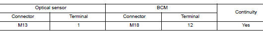
1.CHECK OPTICAL SENSOR POWER SUPPLY INPUT
- Turn power switch ON.
- Turn lighting switch AUTO.
- Check voltage between optical sensor harness connector and ground.
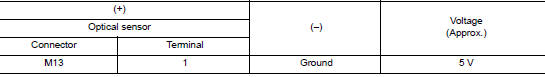
Is the inspection result normal? YES >> GO TO 2.
NO >> GO TO 4.
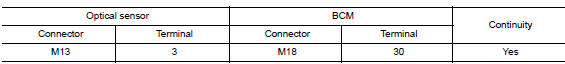
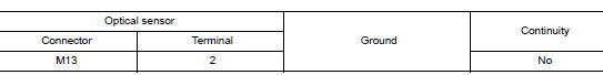
2.CHECK OPTICAL SENSOR GROUND INPUT
Check voltage between optical sensor harness connector and ground.
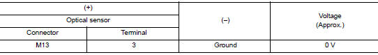
Is the inspection result normal? YES >> GO TO 3.
NO >> GO TO 6.
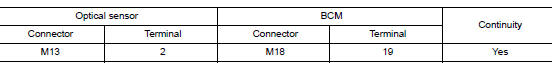
3.CHECK OPTICAL SENSOR SIGNAL OUTPUT
With illuminating the optical sensor, check voltage between optical sensor harness connector and ground.
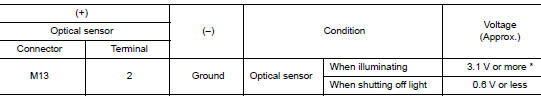
*: Illuminate the optical sensor. The value may be less than the standard if brightness is weak.
Is the inspection result normal? YES >> GO TO 7.
NO >> Replace the optical sensor.
4.CHECK OPTICAL SENSOR OPEN CIRCUIT
- Turn power switch OFF.
- Disconnect optical sensor connector and BCM connector.
- Check continuity between optical sensor harness connector and BCM harness connector.
Is the inspection result normal? YES >> GO TO 5.
NO >> Repair or replace harness.
5.CHECK OPTICAL SENSOR SHORT CIRCUIT
Check continuity between optical sensor harness connector and ground.
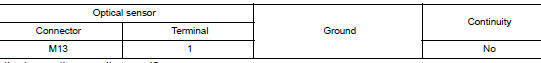
Is the inspection result normal? YES >> Replace BCM. Refer to BCS-75, "Removal and Installation" (with I Key) or BCS-135, "Removal and Installation" (without I Key).
NO >> Repair or replace harness.
6.CHECK OPTICAL SENSOR GROUND OPEN CIRCUIT
- Turn power switch OFF.
- Disconnect optical sensor connector and BCM connector.
- Check continuity between optical sensor harness connector and BCM harness connector.
Is the inspection result normal? YES >> Replace BCM. Refer to BCS-75, "Removal and Installation" (with I Key) or BCS-135, "Removal and Installation" (without I Key).
NO >> Repair or replace harness.
7.CHECK OPTICAL SENSOR SIGNAL OPEN CIRCUIT
- Turn power switch OFF.
- Disconnect optical sensor connector and BCM connector.
- Check continuity between optical sensor harness connector and BCM harness connector.
Is the inspection result normal? YES >> GO TO 8.
NO >> Repair or replace harness.
8.CHECK OPTICAL SENSOR SHORT CIRCUIT
Check continuity between optical sensor harness connector and ground.
Is the inspection result normal? YES >> Replace BCM. Refer to BCS-75, "Removal and Installation" (with I Key) or BCS-135, "Removal and Installation" (without I Key).
NO >> Repair or replace harness.
HAZARD SWITCH
Component Function Check
1.CHECK HAZARD SWITCH SIGNAL BY CONSULT
 CONSULT DATA MONITOR
- Turn power switch ON.
- Select ŌĆ£HAZARD SWŌĆØ of BCM (FLASHER) data monitor item.
- With operating the hazard switch, check the monitor status.
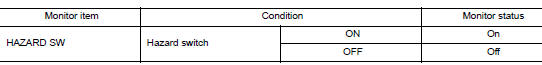
Is the inspection result normal? YES >> Hazard switch circuit is normal.
NO >> Refer to EXL-229, "Diagnosis Procedure".
Diagnosis Procedure
1.CHECK HAZARD SWITCH SIGNAL INPUT
- Turn power switch OFF.
- Disconnect hazard switch connector.
- Check voltage between hazard switch connector and ground.
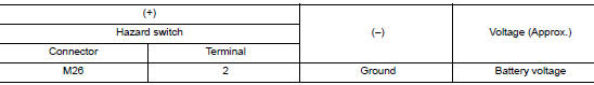
Is the inspection result normal? YES >> GO TO 4.
NO >> GO TO 2.
2.CHECK HAZARD SWITCH SIGNAL OPEN CIRCUIT
- Disconnect BCM connector.
- Check continuity between hazard switch harness connector and BCM harness connector.
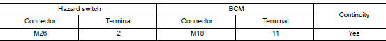
Is the inspection result normal? YES >> GO TO 3.
NO >> Repair or replace harness.
3.CHECK HAZARD SWITCH SIGNAL SHORT CIRCUIT
Check continuity between hazard switch harness connector and ground.
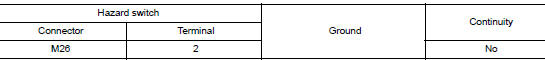
Is the inspection result normal? YES >> Replace BCM. Refer to BCS-75, "Removal and Installation" (with Intelligent Key system) or BCS- 135, "Removal and Installation" (without Intelligent Key system).
NO >> Repair or replace harness.
4.CHECK HAZARD SWITCH GROUND OPEN CIRCUIT
Check continuity between hazard switch harness connector and ground.
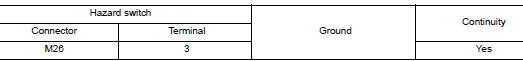
Is the inspection result normal? YES >> Replace hazard switch. Refer to EXL-276, "Removal and Installation".
NO >> Repair or replace harness.
TURN SIGNAL LAMP CIRCUIT
Description
The BCM monitors inputs from the combination switch (lighting and turn signal switch) to determine when to activate the turn signals. The BCM outputs voltage direction to the left and right turn signals during turn signal operation or both during hazard warning operation. The BCM sends a turn signal indicator request to the combination meter via the CAN communication lines.
The BCM performs the fast flasher operation (fail-safe) if any bulb or harness of the turn signal lamp circuit is open.
NOTE: Turn signal lamp blinks at normal speed when using the hazard warning lamp.
Component Function Check
1.CHECK TURN SIGNAL LAMP
 CONSULT
- Select FLASHER of BCM (FLASHER) active test item.
- While operating the test items, check that the turn signal lamp blinks.
LH : Turn signal lamps (LH) ON
RH : Turn signal lamps (RH) ON
Off : Turn signal lamps OFF
Is the inspection result normal? YES >> Turn signal lamp circuit is normal.
NO >> Refer to EXL-231, "Diagnosis Procedure".
Diagnosis Procedure
Regarding Wiring Diagram information, refer to EXL-185, "Wiring Diagram".
1.CHECK TURN SIGNAL LAMP BULB
Check the applicable lamp bulb to be sure the proper bulb standard is in use and the bulb is not open.
Is the bulb OK? YES >> GO TO 2.
NO >> Replace the bulb.
2.CHECK TURN SIGNAL LAMP OUTPUT VOLTAGE
- Turn the ignition switch OFF.
- Disconnect the front combination lamp harness connector or the side turn signal harness connector or the rear combination lamp harness connector in question.
- Turn the ignition switch ON.
- Operate the turn signal switch.
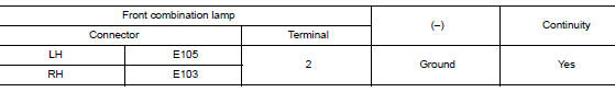
- While the turn signal is operating, check the voltage between the front combination lamp harness connector and ground.

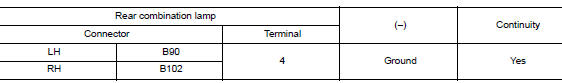
- While the turn signal is operating, check the voltage between the rear combination lamp harness connector and ground.
Are the inspection results normal? YES >> GO TO 5.
NO >> GO TO 3.
3.CHECK TURN SIGNAL LAMP CIRCUIT FOR OPEN
- Turn the ignition switch OFF.
- Disconnect BCM harness connector E29 or B23.
- Check continuity between the BCM harness connector E29 and the front combination lamp harness connector.
- Check continuity between the BCM harness connector B23 and the rear combination lamp harness connector.
Are the inspection results normal? YES >> GO TO 4.
NO >> Repair or replace the harness or connectors.
4.CHECK TURN SIGNAL LAMP SHORT CIRCUIT
- Check continuity between the BCM harness connector E29 and ground.

- Check continuity between the BCM harness connector M20 and ground.
Are the inspection results normal? YES >> Replace BCM. Refer to BCS-75, "Removal and Installation" (with Intelligent Key) or BCS-135, "Removal and Installation" (without Intelligent Key).
NO >> Repair or replace the harness or connectors.
5.CHECK TURN SIGNAL LAMP GROUND CIRCUIT
- Turn the ignition switch OFF.
- Check continuity between the front combination lamp harness connector or the side turn signal harness connector or the rear combination lamp harness connector in question and ground.
- Check continuity between the rear combination lamp harness connector and ground.
Are the inspection results normal? YES >> Replace the malfunctioning lamp.
NO >> Repair or replace the harness or connectors.
B121A FRONT FOG LAMP LH POWER SUPPLY CIRCUIT
DTC Logic
DTC DETECTION LOGIC
|
DTC |
Display Item |
Malfunction detected condition |
Possible causes |
| B121A | FR FOG LAMP LH PWR SPLY CIRC [CIRC SHORT TO GROUND |
|
|
DTC CONFIRMATION PROCEDURE
1.CHECK SELF-DIAGNOSTIC RESULT
 With CONSULT.
- Turn ignition switch ON.
- Perform self-diagnostic result.
Is DTC B121A detected? YES >> Proceed to diagnosis procedure. Refer to EXL-234, "Diagnosis Procedure".
NO >> Inspection End.
Diagnosis Procedure
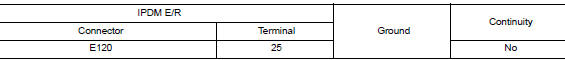
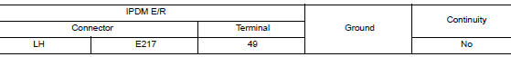
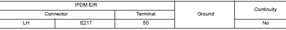
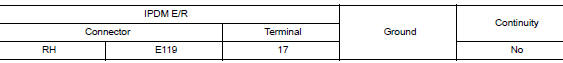
1.CHECK FOG LAMP SHORT CIRCUIT TO GROUND
- Disconnect fog lamp connector and IPDM E/R connector.
- Check continuity between IPDM E/R harness connector and ground.
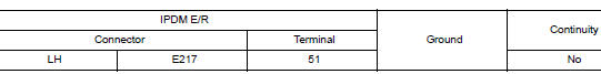
Is the inspection result normal? YES >> GO TO 2.
NO >> Repair or replace harness.
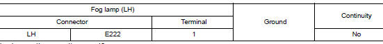
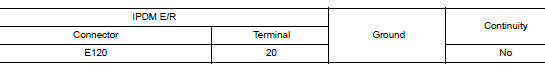
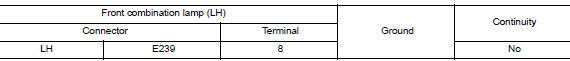
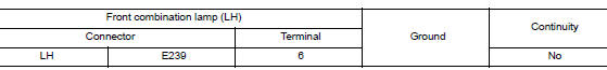
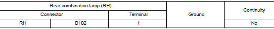
2.CHECK FOG LAMP SHORT CIRCUIT TO GROUND
- Reconnect IPDM E/R connector.
- Check continuity between fog lamp harness connector and ground.
Is the inspection result normal? YES >> Refer to GI-41, "Intermittent Incident".
NO >> Replace IPDM E/R. Refer to PCS-35, "Removal and Installation".
B1231 DAYTIME RUNNING LIGHT RH POWER SUPPLY CIRCUIT
DTC Logic
DTC DETECTION LOGIC
|
DTC |
Display Item |
Malfunction detected condition |
Possible causes |
| B1231 | DTRL RH PWR SPLY CIRC [CIRC SHORT TO GRND] | When a short circuit to ground in the daytime running lamp circuit is detected. |
|
DTC CONFIRMATION PROCEDURE
1.CHECK SELF-DIAGNOSTIC RESULT
With CONSULT.
- Turn ignition switch ON.
- Perform self-diagnostic result.
Is DTC B1231 detected? YES >> Proceed to diagnosis procedure. Refer to EXL-235, "Diagnosis Procedure".
NO >> Inspection End.
Diagnosis Procedure
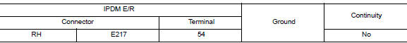
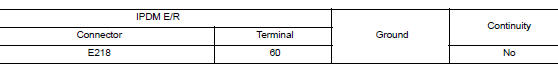
1.CHECK FRONT COMBINATION LAMP SHORT CIRCUIT TO GROUND
- Disconnect front combination lamp connector and IPDM E/R connector.
- Check continuity between IPDM E/R harness connector and ground.
Is the inspection result normal? YES >> GO TO 2.
NO >> Repair or replace harness.
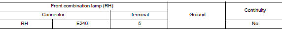
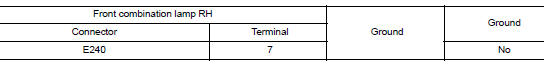
2.CHECK FRONT COMBINATION LAMP SHORT CIRCUIT TO GROUND
- Reconnect IPDM E/R connector.
- Check continuity between front combination lamp harness connector and ground.
Is the inspection result normal? YES >> Refer to GI-41, "Intermittent Incident".
NO >> Replace IPDM E/R. Refer to PCS-35, "Removal and Installation".
B1256 FRONT FOG LAMP RH POWER SUPPLY CIRCUIT
DTC Logic
DTC DETECTION LOGIC
|
DTC |
Display Item |
Malfunction detected condition |
Possible causes |
| B1256 | FR FOG LAMP RH PWR SPLY CIRC [CIRC SHORT TO GRND] | When a short circuit to ground is detected |
|
DTC CONFIRMATION PROCEDURE
1.CHECK SELF-DIAGNOSTIC RESULT
With CONSULT.
- Turn ignition switch ON.
- Perform self-diagnostic result.
Is DTC B1256 detected? YES >> Proceed to diagnosis procedure. Refer to EXL-236, "Diagnosis Procedure".
NO >> Inspection End.
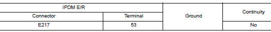
Diagnosis Procedure
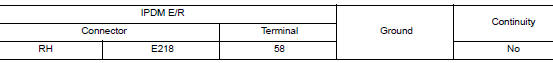
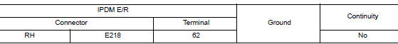
1.CHECK FOG LAMP SHORT CIRCUIT TO GROUND
- Disconnect fog lamp connector and IPDM E/R connector.
- Check continuity between IPDM E/R harness connector and ground.
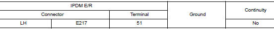
Is the inspection result normal? YES >> GO TO 2.
NO >> Repair or replace harness.
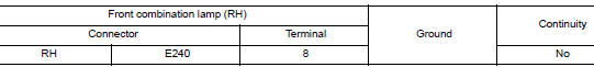
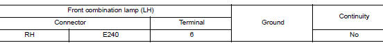
2.CHECK FOG LAMP SHORT CIRCUIT TO GROUND
- Reconnect IPDM E/R connector.
- Check continuity between fog lamp harness connector and ground.
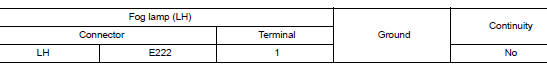
Is the inspection result normal? YES >> Refer to GI-41, "Intermittent Incident".
NO >> Replace IPDM E/R. Refer to PCS-35, "Removal and Installation".
B1C00 HEIGHT SENSOR POWER SUPPLY CIRCUIT
DTC Logic
|
DTC |
Display Item |
Malfunction detected condition |
Possible causes |
| B1C00 | HEIGHT SENSOR PWR SPLY CIRC [CIRC SHORT TO GRND] | When the height sensor power supply circuit is shorted to supply power or shorted to ground |
|
| HEIGHT SENSOR PWR SPLY CIRC [CIRC SHORT TO BATTERY] |
DTC CONFIRMATION PROCEDURE
1.CHECK SELF-DIAGNOSTIC RESULT
With CONSULT.
- Turn ignition switch ON.
- Perform self-diagnostic result.
Is DTC B1C00 detected? YES >> Proceed to diagnosis procedure. Refer to EXL-237, "Diagnosis Procedure".
NO >> Inspection End.
Diagnosis Procedure
1.CHECK HEIGHT SENSOR SHORT CIRCUIT TO GROUND
- Disconnect front and rear height sensor connector and IPDM E/R connector.
- Check continuity between IPDM E/R harness connector and ground.
Is the inspection result normal? YES >> GO TO 2.
NO >> Repair or replace harness.
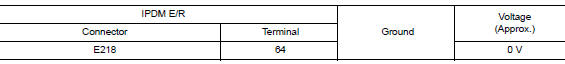
2.CHECK HEIGHT SENSOR SHORT CIRCUIT TO BATTERY VOLTAGE
Check the voltage between IPDM E/R harness connector and ground.
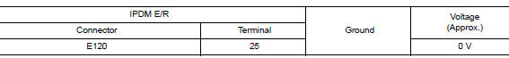
Is the inspection result normal? YES >> GO TO 3.
NO >> Repair or replace harness.
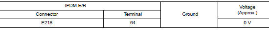
3.CHECK HEIGHT SENSOR SHORT CIRCUIT TO BATTERY VOLTAGE
- Reconnect IPDM E/R connector.
- Check the voltage between IPDM E/R harness connector and ground.
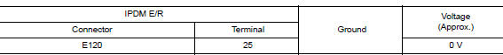
Is the inspection result normal? YES >> Refer to GI-41, "Intermittent Incident".
NO >> Replace IPDM E/R. Refer to PCS-35, "Removal and Installation".
B1C01 FRONT HEIGHT SENSOR SIGNAL
DTC Logic
DTC DETECTION LOGIC
|
DTC |
Display Item |
Malfunction detected condition |
Possible causes |
| B1C01 | FR HEIGHT SENSOR SIGNAL [CIRC SHORT TO BATTERY] |
|
|
| FR HEIGHT SENSOR SIGNAL [CIRC SHORT TO GROUND OR OPEN] | |||
| FR HEIGHT SENSOR SIGNAL [CIRC VOLTAGE OUT OF RANGE] |
DTC CONFIRMATION PROCEDURE
1.SELF-DIAGNOSIS WITH IPDM E/R
- Turn ignition switch ON.
- Check Self-diagnostic result with CONSULT.
Is DTC detected? YES >> Refer to EXL-239, "Diagnosis Procedure".
NO >> Inspection End.
Diagnosis Procedure
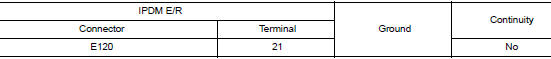
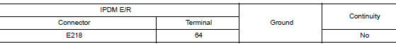
1.CHECK HEIGHT SENSOR SHORT CIRCUIT TO GROUND
- Disconnect front height sensor connector and IPDM E/R connector.
- Check continuity between IPDM E/R harness connector and ground.
Is the inspection result normal? YES >> GO TO 2.
NO >> Repair or replace harness.
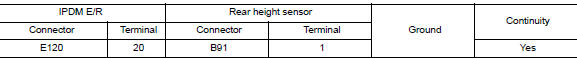
2.CHECK HEIGHT SENSOR SHORT OPEN CIRCUIT
Check the continuity between IPDM E/R harness connector and height sensor connector.
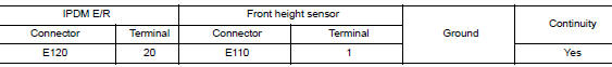
Is the inspection result normal? YES >> GO TO 3.
NO >> Repair or replace harness.
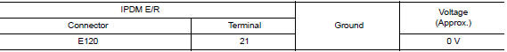
3.CHECK HEIGHT SENSOR SHORT CIRCUIT TO BATTERY VOLTAGE
Check the voltage between IPDM E/R harness connector and ground.
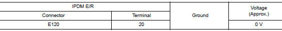
Is the inspection result normal?
YES >> GO TO 3.
NO >> Repair or replace harness.
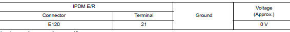
4.CHECK HEIGHT SENSOR SHORT CIRCUIT TO BATTERY VOLTAGE
- Reconnect IPDM E/R connector.
- Check the voltage between IPDM E/R harness connector and ground.
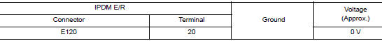
Is the inspection result normal? YES >> Refer to GI-41, "Intermittent Incident".
NO >> Replace IPDM E/R. Refer to PCS-35, "Removal and Installation".
B1C02 REAR HEIGHT SENSOR SIGNAL
DTC Logic
DTC DETECTION LOGIC
|
DTC |
Display Item |
Malfunction detected condition |
Possible causes |
| B1C02 | RR HEIGHT SENSOR SIGNAL [CIRC SHORT TO BATTERY] |
|
|
| RR HEIGHT SENSOR SIGNAL [CIRC SHORT TO GROUND OR OPEN] | |||
| RR HEIGHT SENSOR SIGNAL [CIRC VOLTAGE OUT OF RANGE] |
DTC CONFIRMATION PROCEDURE
1.SELF-DIAGNOSIS WITH IPDM E/R
- Turn ignition switch ON.
- Check Self-diagnostic result with CONSULT.
Is DTC detected? YES >> Refer to EXL-241, "Diagnosis Procedure".
NO >> Inspection End.
Diagnosis Procedure
1.CHECK HEIGHT SENSOR SHORT CIRCUIT TO GROUND
- Disconnect rear height sensor connector and IPDM E/R connector.
- Check continuity between IPDM E/R harness connector and ground.
Is the inspection result normal? YES >> GO TO 2.
NO >> Repair or replace harness.
2.CHECK HEIGHT SENSOR SHORT OPEN CIRCUIT
Check the continuity between IPDM E/R harness connector and height sensor connector.
Is the inspection result normal? YES >> GO TO 3.
NO >> Repair or replace harness.
3.CHECK HEIGHT SENSOR SHORT CIRCUIT TO BATTERY VOLTAGE
Check the voltage between IPDM E/R harness connector and ground.
Is the inspection result normal?
YES >> GO TO 3.
NO >> Repair or replace harness.
4.CHECK HEIGHT SENSOR SHORT CIRCUIT TO BATTERY VOLTAGE
- Reconnect IPDM E/R connector.
- Check the voltage between IPDM E/R harness connector and ground.
Is the inspection result normal? YES >> Refer to GI-41, "Intermittent Incident".
NO >> Replace IPDM E/R. Refer to PCS-35, "Removal and Installation".
B1C07 AIMING MOTOR DRIVE SIGNAL
DTC Logic
DTC DETECTION LOGIC
|
DTC |
Display Item |
Malfunction detected condition |
Possible causes |
| B1C07 | AIMING MOTOR DRIVE SIGNAL [CIRC SHORT TO GRND] |
|
|
| AIMING MOTOR DRIVE SIGNAL [CIRC SHORT TO BATTERY] | |||
| AIMING MOTOR DRIVE SIGNAL [SIGNAL COMPARE FAILURE] |
DTC CONFIRMATION PROCEDURE
1.CHECK SELF-DIAGNOSTIC RESULT
 With CONSULT.
- Turn ignition switch ON.
- Perform self-diagnostic result.
Is DTC B1C07 detected? YES >> Proceed to diagnosis procedure. Refer to EXL-243, "Diagnosis Procedure".
NO >> Inspection End.
Diagnosis Procedure
1.CHECK HEADLAMP AIMING MOTOR DRIVE SIGNAL SHORT CIRCUIT TO GROUND
- Disconnect LH and RH headlamp aiming motor connectors and IPDM E/R connector.
- Check continuity between IPDM E/R harness connector and ground.
Is the inspection result normal? YES >> GO TO 2.
NO >> Repair or replace harness.
2.CHECK HEADLAMP AIMING MOTOR DRIVE SIGNAL SHORT CIRCUIT TO BATTERY VOLTAGE
Check the voltage between IPDM E/R harness connector and ground.
Is the inspection result normal? YES >> GO TO 3.
NO >> Repair or replace harness.
3.CHECK HEADLAMP AIMING MOTOR DRIVE SIGNAL SHORT CIRCUIT TO BATTERY VOLTAGE
- Reconnect IPDM E/R connector.
- Check the voltage between IPDM E/R harness connector and ground.
Is the inspection result normal? YES >> Refer to GI-41, "Intermittent Incident".
NO >> Replace IPDM E/R. Refer to PCS-35, "Removal and Installation".
B20CB DAYTIME RUNNING LIGHT LH POWER SUPPLY CIRCUIT
DTC Logic
DTC DETECTION LOGIC
|
DTC |
Display Item |
Malfunction detected condition |
Possible causes |
| B20CB | DTRL LH PWR SPLY CIRC [CIRC SHORT TO GRND] | When a short circuit to ground is detected. |
|
DTC CONFIRMATION PROCEDURE
1.CHECK SELF-DIAGNOSTIC RESULT
 With CONSULT.
- Turn ignition switch ON.
- Perform self-diagnostic result.
Is DTC B02CB detected? YES >> Proceed to diagnosis procedure. Refer to EXL-245, "Diagnosis Procedure".
NO >> Inspection End.
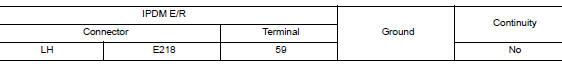
Diagnosis Procedure
1.CHECK FRONT COMBINATION LAMP SHORT CIRCUIT TO GROUND
- Disconnect front combination lamp connector and IPDM E/R connector.
- Check continuity between IPDM E/R harness connector and ground.
Is the inspection result normal? YES >> GO TO 2.
NO >> Repair or replace harness.
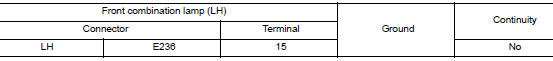
2.CHECK FRONT COMBINATION LAMP SHORT CIRCUIT TO GROUND
- Reconnect IPDM E/R connector.
- Check continuity between fog lamp harness connector and ground.
Is the inspection result normal? YES >> Refer to GI-41, "Intermittent Incident".
NO >> Replace IPDM E/R. Refer to PCS-35, "Removal and Installation".
B20CE HEADLAMP (HI) LH POWER SUPPLY CIRCUIT
DTC Logic
DTC DETECTION LOGIC
|
DTC |
Display Item |
Malfunction detected condition |
Possible causes |
| B20CE | DTRL LH PWR SPLY CIRC [CIRC SHORT TO GRND] |
|
|
DTC CONFIRMATION PROCEDURE
1.CHECK SELF-DIAGNOSTIC RESULT
With CONSULT.
- Turn ignition switch ON.
- Perform self-diagnostic result.
Is DTC B20CE detected? YES >> Proceed to diagnosis procedure. Refer to EXL-246, "Diagnosis Procedure".
NO >> Inspection End.
Diagnosis Procedure
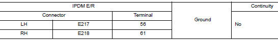
1.CHECK HEAD LAMP SHORT CIRCUIT TO GROUND
- Disconnect front combination lamp connector and IPDM E/R connector.
- Check continuity between IPDM E/R harness connector and ground.
Is the inspection result normal? YES >> GO TO 2.
NO >> Repair or replace harness.
2.CHECK HEAD LAMP SHORT CIRCUIT TO GROUND
- Reconnect IPDM E/R connector.
- Check continuity between front combination lamp harness connector and ground.
Is the inspection result normal? YES >> Refer to GI-41, "Intermittent Incident".
NO >> Replace IPDM E/R. Refer to PCS-35, "Removal and Installation".
B20CF HEADLAMP (HI) RH POWER SUPPLY CIRCUIT
DTC Logic
DTC DETECTION LOGIC
|
DTC |
Display Item |
Malfunction detected condition |
Possible causes |
| B20CF | HL (HI) RH PWR SPLY CIRC [CIRC SHORT TO GRND] |
|
|
DTC CONFIRMATION PROCEDURE
1.CHECK SELF-DIAGNOSTIC RESULT
With CONSULT.
- Turn ignition switch ON.
- Perform self-diagnostic result.
Is DTC B20CF detected? YES >> Proceed to diagnosis procedure. Refer to EXL-247, "Diagnosis Procedure".
NO >> Inspection End.
Diagnosis Procedure
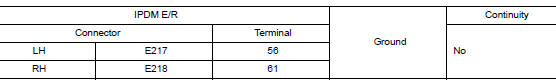
1.CHECK HEAD LAMP SHORT CIRCUIT TO GROUND
- Disconnect front combination lamp connector and IPDM E/R connector.
- Check continuity between IPDM E/R harness connector and ground.
Is the inspection result normal? YES >> GO TO 2.
NO >> Repair or replace harness.
2.CHECK HEAD LAMP SHORT CIRCUIT TO GROUND
- Reconnect IPDM E/R connector.
- Check continuity between front combination lamp harness connector and ground.
Is the inspection result normal? YES >> Refer to GI-41, "Intermittent Incident".
NO >> Replace IPDM E/R. Refer to PCS-35, "Removal and Installation".
B20D0 HEADLAMP (LO) LH POWER SUPPLY CIRCUIT
DTC Logic
DTC DETECTION LOGIC
|
DTC |
Display Item |
Malfunction detected condition |
Possible causes |
| B20D0 | HI (LO) RH PWR SPLY CIRC [CIRC SHORT TO GRND] |
|
|
DTC CONFIRMATION PROCEDURE
1.CHECK SELF-DIAGNOSTIC RESULT
With CONSULT.
- Turn ignition switch ON.
- Perform self-diagnostic result.
Is DTC B20D0 detected? YES >> Proceed to diagnosis procedure. Refer to EXL-248, "Diagnosis Procedure".
NO >> Inspection End.
Diagnosis Procedure
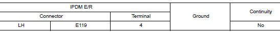
1.CHECK FRONT COMBINATION LAMP SHORT CIRCUIT TO GROUND
- Disconnect front combination lamp connector and IPDM E/R connector.
- Check continuity between IPDM E/R harness connector and ground.
Is the inspection result normal? YES >> GO TO 2.
NO >> Repair or replace harness.
2.CHECK FRONT COMBINATION LAMP SHORT CIRCUIT TO GROUND
- Reconnect IPDM E/R connector.
- Check continuity between front combination lamp harness connector and ground.
Is the inspection result normal? YES >> Refer to GI-41, "Intermittent Incident".
NO >> Replace IPDM E/R. Refer to PCS-35, "Removal and Installation".
B20D1 HEADLAMP (LO) RH POWER SUPPLY CIRCUIT
DTC Logic
DTC DETECTION LOGIC
|
DTC |
Display Item |
Malfunction detected condition |
Possible causes |
| B20D1 | HL (LO) RH PWR SPLY CIRC [CIRC SHORT TO GRND] |
|
|
DTC CONFIRMATION PROCEDURE
1.CHECK SELF-DIAGNOSTIC RESULT
With CONSULT.
- Turn ignition switch ON.
- Perform self-diagnostic result.
Is DTC B20D1 detected? YES >> Proceed to diagnosis procedure. Refer to EXL-249, "Diagnosis Procedure".
NO >> Inspection End.
Diagnosis Procedure
1.CHECK FRONT COMBINATION LAMP SHORT CIRCUIT TO GROUND
- Disconnect front combination lamp connector and IPDM E/R connector.
- Check continuity between IPDM E/R harness connector and ground.
Is the inspection result normal? YES >> GO TO 2.
NO >> Repair or replace harness.
2.CHECK FRONT COMBINATION LAMP SHORT CIRCUIT TO GROUND
- Reconnect IPDM E/R connector.
- Check continuity between front combination lamp harness connector and ground.
Is the inspection result normal? YES >> Refer to GI-41, "Intermittent Incident".
NO >> Replace IPDM E/R. Refer to PCS-35, "Removal and Installation".
B20D2 PARKING LAMP POWER SUPPLY CIRCUIT
DTC Logic
DTC DETECTION LOGIC
|
DTC |
Display Item |
Malfunction detected condition |
Possible causes |
| B20D2 | PARKING LAMP PWR SPLY CIRC [CIRC SHORT TO GROUND] | When a short to ground is detected in the parking lamp power supply circuit. |
|
DTC CONFIRMATION PROCEDURE
1.CHECK SELF-DIAGNOSTIC RESULT
With CONSULT.
- Turn ignition switch ON.
- Perform self-diagnostic result.
Is DTC B20D2 detected? YES >> Proceed to diagnosis procedure. Refer to EXL-250, "Diagnosis Procedure".
NO >> Inspection End.
Diagnosis Procedure
1.CHECK FRONT COMBINATION LAMP SHORT CIRCUIT TO GROUND
- Disconnect front combination lamp connectors and IPDM E/R connector.
- Check continuity between IPDM E/R harness connector and ground.
Is the inspection result normal? YES >> GO TO 2.
NO >> Repair or replace harness.
2.CHECK FRONT COMBINATION LAMP SHORT CIRCUIT TO GROUND
- Reconnect IPDM E/R connector.
- Check continuity between front combination lamp harness connector and ground.
Is the inspection result normal? YES >> Refer to GI-41, "Intermittent Incident".
NO >> Replace IPDM E/R. Refer to PCS-35, "Removal and Installation".
B20D4 TAIL LAMP LH POWER SUPPLY CIRCUIT
DTC Logic
DTC DETECTION LOGIC
|
DTC |
Display Item |
Malfunction detected condition |
Possible causes |
|
B20D4 |
TAIL LAMP LH PWR SPLY CIRC [CIRC SHORT TO GRND] |
|
|
DTC CONFIRMATION PROCEDURE
1.CHECK SELF-DIAGNOSTIC RESULT
With CONSULT.
- Turn ignition switch ON.
- Perform self-diagnostic result.
Is DTC B20D4 detected? YES >> Proceed to diagnosis procedure. Refer to EXL-251, "Diagnosis Procedure".
NO >> Inspection End.
Diagnosis Procedure
1.CHECK TAIL LAMP SHORT CIRCUIT TO GROUND
- Disconnect rear combination lamp (LH), license plate lamps, back up lamp connectors and IPDM E/R connector.
- Check continuity between IPDM E/R harness connector and ground.
Is the inspection result normal? YES >> GO TO 2.
NO >> Repair or replace harness.
2.CHECK TAIL LAMP SHORT CIRCUIT TO GROUND
- Reconnect IPDM E/R connector.
- Check continuity between rear combination lamp harness connector and ground.
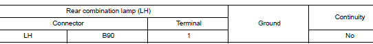
Is the inspection result normal? YES >> Refer to GI-41, "Intermittent Incident".
NO >> Replace IPDM E/R. Refer to PCS-35, "Removal and Installation".
B20D5 TAIL LAMP RH POWER SUPPLY CIRCUIT
DTC Logic
DTC DETECTION LOGIC
|
DTC |
Display Item |
Malfunction detected condition |
Possible causes |
| B20D5 | TAIL LAMP RH PWR SPLY CIRC [CIRC SHORT TO GRND] | When a short circuit to ground is detected in the tail lamp supply voltage circuit |
|
DTC CONFIRMATION PROCEDURE
1.CHECK SELF-DIAGNOSTIC RESULT
With CONSULT.
- Turn ignition switch ON.
- Perform self-diagnostic result.
Is DTC B20D5 detected? YES >> Proceed to diagnosis procedure. Refer to EXL-252, "Diagnosis Procedure".
NO >> Inspection End.
Diagnosis Procedure
1.CHECK TAIL LAMP SHORT CIRCUIT TO GROUND
- Disconnect rear combination lamp (RH), back up lamp connectors and IPDM E/R connector.
- Check continuity between IPDM E/R harness connector and ground.
Is the inspection result normal? YES >> GO TO 2.
NO >> Repair or replace harness.
2.CHECK TAIL LAMP SHORT CIRCUIT TO GROUND
- Reconnect IPDM E/R connector.
- Check continuity between rear combination lamp harness connector and ground.
Is the inspection result normal? YES >> Refer to GI-41, "Intermittent Incident".
NO >> Replace IPDM E/R. Refer to PCS-35, "Removal and Installation".
B20DB HEIGHT SENSOR INITIALIZE NOT DONE
DTC Logic
DTC DETECTION LOGIC
|
DTC |
Display Item |
Malfunction detected condition |
Possible causes |
| B20DB | HEIGHT SENS INTIALIZE NOT DONE [MISSING CALIBRATION] | Sensor initialization is not complete |
|
| HEIGHT SENS INTIALIZE NOT DONE [NOT CONFIGURED] |
DTC CONFIRMATION PROCEDURE
1.PERFORM SELF-DIAGNOSIS
CONSULT
- Turn ignition switch ON.
- Perform self-diagnosis of IPDM E/R using CONSULT.
Is DTC B20DB detected? YES >> Refer to EXL-253, "Diagnosis Procedure".
NO >> Inspection End.
Diagnosis Procedure
1.CHECK SELF-DIAGNOSTIC RESULT
With CONSULT.
- Turn ignition ON.
- Select ŌĆ£SENSOR INITIALIZEŌĆØ of IPDM E/R Work Support item.
Is DTC B20DB detected? YES >> Replace IPDM E/R. Refer to PCS-35, "Removal and Installation".
NO >> Inspection End.
B20E2 LED HEADLAMP RH
DTC Logic
DTC DETECTION LOGIC
|
DTC |
Display Item |
Malfunction detected condition |
Possible causes |
| B20E2 | LED HEADLAMP RH [CMPNENT INTERNAL MLFNCTN] |
|
|
DTC CONFIRMATION PROCEDURE
1.SELF-DIAGNOSIS WITH IPDM E/R
- Turn ignition switch ON.
- Check Self-diagnostic result with CONSULT.
Is DTC detected? YES >> Refer to EXL-254, "Diagnosis Procedure".
NO >> Inspection End.
Diagnosis Procedure
1.CHECK FRONT COMBINATION LAMP RH SHORT CIRCUIT TO GROUND
- Disconnect front combination lamp RH connector and IPDM E/R connector.
- Check continuity between IPDM E/R harness connector and ground.
Is the inspection result normal? YES >> GO TO 2.
NO >> Repair or replace harness.
2.CHECK FRONT COMBINATION LAMP RH SHORT CIRCUIT TO GROUND
- Reconnect IPDM E/R connector.
- Check continuity between front combination lamp RH harness connector and ground.
Is the inspection result normal? YES >> Refer to GI-41, "Intermittent Incident".
NO >> Replace IPDM E/R. Refer to PCS-35, "Removal and Installation".
B20E3 LED HEADLAMP LH
DTC Logic
DTC DETECTION LOGIC
|
DTC |
Display Item |
Malfunction detected condition |
Possible causes |
| B20E3 | LED HEADLAMP LH [CMPNENT INTERNAL MLFNCTN] |
|
|
DTC CONFIRMATION PROCEDURE
1.SELF-DIAGNOSIS WITH IPDM E/R
- Turn ignition switch ON.
- Check Self-diagnostic result with CONSULT.
Is DTC detected? YES >> Refer to EXL-255, "Diagnosis Procedure".
NO >> Inspection End.
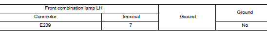
Diagnosis Procedure
1.CHECK FRONT COMBINATION LAMP LH SHORT CIRCUIT TO GROUND
- Disconnect front combination lamp LH connector and IPDM E/R connector.
- Check continuity between IPDM E/R harness connector and ground.
Is the inspection result normal? YES >> GO TO 2.
NO >> Repair or replace harness.
2.CHECK FRONT COMBINATION LAMP LH SHORT CIRCUIT TO GROUND
- Reconnect IPDM E/R connector.
- Check continuity between front combination lamp LH harness connector and ground.
Is the inspection result normal? YES >> Refer to GI-41, "Intermittent Incident".
NO >> Replace IPDM E/R. Refer to PCS-35, "Removal and Installation".
 Basic inspection
DIAGNOSIS AND REPAIR WORKFLOW
Work Flow
OVERALL SEQUENCE
DETAILED FLOW
1.GET INFORMATION FOR SYMPTOM
Get detailed information from the customer about the symptom (the
condition an ...
 Symptom diagnosis
EXTERIOR LIGHTING SYSTEM SYMPTOMS
Symptom Table
CAUTION:
Perform the self-diagnosis with CONSULT before the symptom diagnosis. Perform
the trouble diagnosis
if any DTC is detected.
NORM ...
Other materials:
P0139 HO2S2
DTC Description
DTC DETECTION LOGIC
The heated oxygen sensor 2 has a much longer switching time
between rich and lean than the air fuel ratio (A/F) sensor 1. The oxygen
storage capacity of the three way catalyst 1 causes the longer
switching time. To judge the malfunctions of heated oxygen sens ...
NISSAN vehicle immobilizer system
The NISSAN Vehicle Immobilizer system will not
allow the engine to start without the use of the
registered key.
If the engine fails to start using a registered key
(for example, when interference is caused by
another registered key, an automated toll road
device or automatic payment device o ...
Precaution
Precaution for Supplemental Restraint System (SRS) "AIR BAG" and "SEAT
BELT
PRE-TENSIONER"
The Supplemental Restraint System such as ŌĆ£AIR BAGŌĆØ and ŌĆ£SEAT BELT PRE-TENSIONERŌĆØ,
used along
with a front seat belt, helps to reduce the risk or severity of injury to the
...
