Nissan Rogue Service Manual: DTC/circuit diagnosis
U1000 CAN COMM CIRCUIT
Description
CAN (Controller Area Network) is a serial communication system for real time application. It is an on-vehicle multiplex communication system with high data communication speed and excellent error detection ability.
Many electronic control units are equipped onto vehicles, and each control unit shares information and links with other control units during operation (not independent). In CAN communication, control units are connected with two communication lines (CAN-H line, CAN-L line) allowing a high rate of information transmission with less wiring. Each control unit transmits/receives data but selectively reads required data only. Refer to LAN-32, "CAN COMMUNICATION SYSTEM : CAN Communication Signal Chart".
DTC Logic
DTC DETECTION LOGIC
|
DTC |
Items (CONSULT screen terms) |
DTC detection condition |
Possible cause |
| U1000 | CAN COMM CIRCUIT | When A/C auto amp. is not transmitting or receiving CAN communication signal for 2 or more seconds. | CAN communication system |
DTC CONFIRMATION PROCEDURE
1.PERFORM SELF-DIAGNOSIS
 With CONSULT
- Turn ignition switch ON and wait for 2 seconds or more.
- Using CONSULT, perform тАЬSelf Diagnostic ResultтАЭ of тАЬHVACтАЭ.
- Check if any DTC No. is displayed in the self-diagnosis results.
Is DTC detected? YES >> Refer to HAC-152, "Diagnosis Procedure".
NO >> Refer to GI-41, "Intermittent Incident".
Diagnosis Procedure
1.CHECK CAN COMMUNICATION SYSTEM
Check CAN communication system. Refer to LAN-17, "Trouble Diagnosis Flow Chart".
>> Inspection End.
U1010 CONTROL UNIT (CAN)
Description
Initial diagnosis of A/C auto amp.
DTC Logic
DTC DETECTION LOGIC
|
DTC |
Items (CONSULT screen terms) |
DTC detection condition |
Possible cause |
| U1010 | CONTROL UNIT (CAN) | When detecting error during the initial diagnosis of CAN controller of front air control. | Front air control |
DTC CONFIRMATION PROCEDURE
1.PERFORM SELF-DIAGNOSIS
With CONSULT
- Turn ignition switch ON.
- Using CONSULT, perform тАЬSelf Diagnostic ResultтАЭ of тАЬHVACтАЭ.
- Check if any DTC No. is displayed in the self-diagnosis results.
Is DTC detected? YES >> Refer to HAC-153, "Diagnosis Procedure".
NO >> Inspection End.
Diagnosis Procedure
1.REPLACE FRONT AIR CONTROL
Replace front air control. Refer to HAC-181, "Removal and Installation".
>> Inspection End.
B24A4 INTAKE SENSOR
DTC Logic
DTC DETECTION LOGIC
NOTE:
- If DTC is displayed along with DTC U1000, first perform the trouble diagnosis for DTC U1000. Refer to HAC- 152, "DTC Logic".
- If DTC is displayed along with DTC U1010, first perform the trouble diagnosis for DTC U1010. Refer to HAC- 153, "DTC Logic".
|
DTC |
Items (CONSULT screen terms) |
DTC detection condition |
Possible cause |
| B24A4 | INTAKE SENSOR | The intake sensor recognition temperature is too high. |
|
DTC CONFIRMATION PROCEDURE
1.PERFORM DTC CONFIRMATION PROCEDURE
With CONSULT
- Turn ignition switch ON.
- Using CONSULT, perform тАЬSelf Diagnostic ResultтАЭ of тАЬHVACтАЭ.
- Check if any DTC No. is displayed in the self-diagnosis results.
Is DTC detected? YES >> Refer to HAC-154, "Diagnosis Procedure".
NO >> Inspection End.
Diagnosis Procedure
Regarding Wiring Diagram information, refer to HAC-136, "Wiring Diagram".
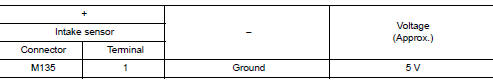
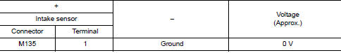
1.CHECK INTAKE SENSOR POWER SUPPLY
- Turn ignition switch OFF.
- Disconnect intake sensor connector.
- Turn ignition switch ON.
- Check voltage between intake sensor harness connector and ground.
Is the inspection result normal? YES >> GO TO 2.
NO >> GO TO 4.
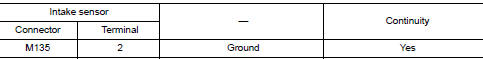
2.CHECK INTAKE SENSOR GROUND CIRCUIT
- Turn ignition switch OFF.
- Check continuity between intake sensor harness connector and ground.
Is the inspection result normal? YES >> GO TO 3.
NO >> Repair harness or connector.
3.CHECK INTAKE SENSOR
Check intake sensor. Refer to HAC-155, "Component Inspection".
Is the inspection result normal? YES >> Replace front air control. Refer to HAC-181, "Removal and Installation".
NO >> Replace intake sensor. Refer to HAC-182, "Removal and Installation".
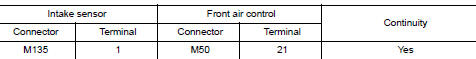
4.CHECK INTAKE SENSOR POWER SUPPLY CIRCUIT FOR OPEN
- Turn ignition switch OFF.
- Disconnect front air control connector.
- Check continuity between intake sensor harness connector and front air control harness connector.
Is the inspection result normal? YES >> GO TO 5.
NO >> Repair harness or connector.
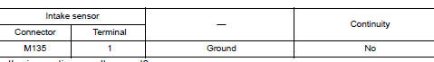
5.CHECK INTAKE SENSOR POWER SUPPLY CIRCUIT FOR SHORT TO GROUND
Check continuity between intake sensor harness connector and ground.
Is the inspection result normal? YES >> GO TO 6.
NO >> Repair harness or connector.
6.CHECK INTAKE SENSOR POWER SUPPLY CIRCUIT FOR SHORT TO VOLTAGE
- Turn ignition switch ON.
- Check voltage between intake sensor harness connector and ground.
Is the inspection result normal? YES >> Replace front air control. Refer to HAC-181, "Removal and Installation".
NO >> Repair harness or connector.
Component Inspection
1.CHECK INTAKE SENSOR
- Turn ignition switch OFF.
- Disconnect intake sensor connector.
- Check resistance between intake sensor terminals.
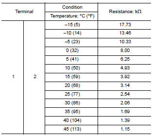
Is the inspection result normal? YES >> Inspection End.
NO >> Replace intake sensor. Refer to HAC-182, "Removal and Installation".
B24B7 INTAKE DOOR MOTOR
DTC Logic
DTC DETECTION LOGIC
NOTE:
- If DTC is displayed along with DTC U1000, first perform the trouble diagnosis for DTC U1000. Refer to HAC- 152, "DTC Logic".
- If DTC is displayed along with DTC U1010, first perform the trouble diagnosis for DTC U1010. HAC-153, "DTC Logic".
|
DTC |
Items (CONSULT screen terms) |
DTC detection condition |
Possible cause |
| B24B7 | INTAKE DOOR MOTOR | Short or open circuit of intake door motor drive signal. |
|
DTC CONFIRMATION PROCEDURE
1.PERFORM DTC CONFIRMATION PROCEDURE
 With CONSULT
- Start engine.
- Select тАЬSelf Diagnostic ResultтАЭ mode of тАЬHVACтАЭ using CONSULT.
- Check DTC.
Is DTC detected? YES >> Refer to HAC-157, "Diagnosis Procedure".
NO >> Inspection End.
Diagnosis Procedure
Regarding Wiring Diagram information, refer to HAC-136, "Wiring Diagram".
NOTE: This DTC can be set if the BCM is placed in transit mode. Confirm if the DTC is CURRENT or PAST. If PAST, perform the following steps before carrying out Diagnosis Procedure.
- Clear DTC using CONSULT. Refer to HAC-22, "CONSULT Function (HVAC)".
- Perform OPERATION INSPECTION. Refer to HAC-48, "Work Procedure".
- Perform тАЬSelf Diagnostic ResultтАЭ of тАЬHVACтАЭ using CONSULT. Refer to HAC-22, "CONSULT Function (HVAC)".
- If DTC resets, proceed with Diagnosis Procedure.
1.CHECK INTAKE DOOR MOTOR POWER SUPPLY
- Turn ignition switch OFF.
- Disconnect intake door motor connector.
- Turn ignition switch ON.
- Check voltage between intake door motor harness connector and ground.
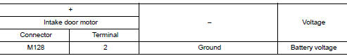
Is the inspection result normal? YES >> GO TO 3.
NO >> GO TO 2.
2.CHECK INTAKE DOOR MOTOR POWER SUPPLY CIRCUIT FOR OPEN
- Disconnect front air control connector.
- Check continuity between intake door motor harness connector and front air control harness connector.
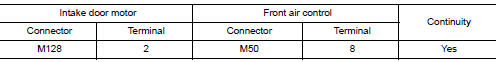
Is the inspection result normal? YES >> Replace front air control. Refer to HAC-181, "Removal and Installation".
NO >> Repair harness or connector.
3.CHECK INTAKE DOOR MOTOR DRIVE SIGNAL CIRCUIT FOR OPEN
- Turn ignition switch OFF.
- Disconnect front air control connector.
- Check continuity between intake door motor harness connector and front air control harness connector.
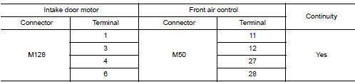
Is the inspection result normal? YES >> GO TO 4.
NO >> Repair harness or connector.
4.CHECK INTAKE DOOR MOTOR DRIVE SIGNAL CIRCUIT FOR SHORT
Check continuity between intake door motor harness connector and front air control harness connector.
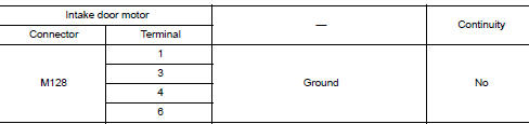
Is the inspection result normal? YES >> GO TO 5.
NO >> Repair harness or connector.
5.CHECK INTAKE DOOR MOTOR
Check intake door motor. Refer to HAC-185, "INTAKE DOOR MOTOR : Removal and Installation".
Is the inspection result normal? YES >> Replace front air control. Refer to HAC-181, "Removal and Installation".
NO >> Replace intake door motor. Refer to HAC-185, "INTAKE DOOR MOTOR : Removal and Installation".
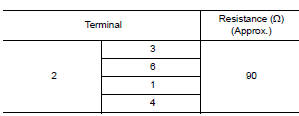
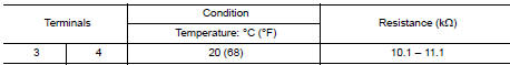
Component Inspection (Motor)
1.CHECK INTAKE DOOR MOTOR
- Remove intake door motor. Refer to HAC-185, "INTAKE DOOR MOTOR : Removal and Installation".
- Check resistance between intake door motor terminals. Refer to applicable table for the normal value.
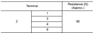
Is the inspection result normal? YES >> Inspection End.
NO >> Replace intake door motor. Refer to HAC-185, "INTAKE DOOR MOTOR : Removal and Installation".
B24B9 MODE DOOR MOTOR
DTC Logic
DTC DETECTION LOGIC
NOTE:
- If DTC is displayed along with DTC U1000, first perform the trouble diagnosis for DTC U1000. Refer to HAC- 152, "DTC Logic".
- If DTC is displayed along with DTC U1010, first perform the trouble diagnosis for DTC U1010. HAC-153, "DTC Logic".
- If mode door motors DTC (B27A6 тАУ B27A9) are detected, there is probably a disconnected connector or an open circuit in mode door motor drive power supply harness.
|
DTC |
Items (CONSULT screen terms) |
DTC detection condition |
Possible cause |
| B24B9 | MODE DOOR MOTOR | Short or open circuit of mode door motor drive signal. |
|
DTC CONFIRMATION PROCEDURE
1.PERFORM DTC CONFIRMATION PROCEDURE
 With CONSULT
- Turn ignition switch ON.
- Select тАЬSelf Diagnostic ResultтАЭ mode of тАЬHVACтАЭ using CONSULT.
- Check DTC.
Is DTC detected? YES >> Refer to HAC-160, "Diagnosis Procedure".
NO >> Inspection End.
Diagnosis Procedure
Regarding Wiring Diagram information, refer to HAC-136, "Wiring Diagram".
NOTE: This DTC can be set if the BCM is placed in transit mode. Confirm if the DTC is CURRENT or PAST. If PAST, perform the following steps before carrying out Diagnosis Procedure.
- Clear DTC using CONSULT. Refer to HAC-22, "CONSULT Function (HVAC)".
- Perform OPERATION INSPECTION. Refer to HAC-48, "Work Procedure".
- Perform тАЬSelf Diagnostic ResultтАЭ of тАЬHVACтАЭ using CONSULT. Refer to HAC-22, "CONSULT Function (HVAC)".
- If DTC resets, proceed with Diagnosis Procedure.
1.CHECK MODE DOOR MOTOR POWER SUPPLY
- Turn ignition switch OFF.
- Disconnect mode door motor connector.
- Turn ignition switch ON.
- Check voltage between mode door motor harness connector and ground.
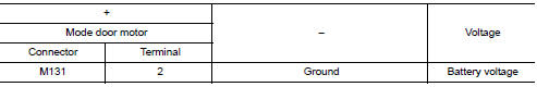
Is the inspection result normal? YES >> GO TO 3.
NO >> GO TO 2.
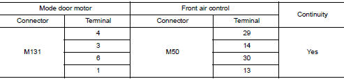
2.CHECK MODE DOOR MOTOR POWER SUPPLY CIRCUIT FOR OPEN
- Disconnect front air control connector.
- Check continuity between mode door motor harness connector and front air control harness connector.
Is the inspection result normal? YES >> Replace front air control. Refer to HAC-181, "Removal and Installation".
NO >> Repair harness or connector.
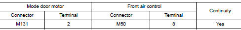
3.CHECK MODE DOOR MOTOR DRIVE SIGNAL CIRCUIT FOR OPEN
- Turn ignition switch OFF.
- Disconnect front air control connector.
- Check continuity between mode door motor harness connector and front air control harness connector.
Is the inspection result normal? YES >> GO TO 4.
NO >> Repair harness or connector.
4.CHECK MODE DOOR MOTOR DRIVE SIGNAL CIRCUIT FOR SHORT
Check continuity between mode door motor harness connector and ground.
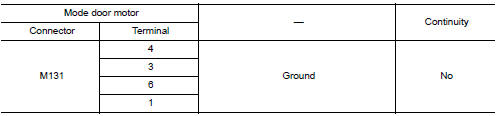
Is the inspection result normal? YES >> GO TO 5.
NO >> Repair harness or connector.
5.CHECK MODE DOOR MOTOR
Check mode door motor. Refer to HAC-161, "Component Inspection".
Is the inspection result normal? YES >> Replace front air control. Refer to HAC-181, "Removal and Installation".
NO >> Replace mode door motor. Refer to HAC-185, "MODE DOOR MOTOR : Removal and Installation".
Component Inspection
1.CHECK MODE DOOR MOTOR
- Remove mode door motor. Refer to HAC-185, "MODE DOOR MOTOR : Removal and Installation".
- . Check resistance between mode door motor terminals. Refer to applicable table for the normal value.
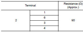
Is the inspection result normal? YES >> Inspection End.
NO >> Replace mode door motor. Refer to HAC-185, "MODE DOOR MOTOR : Removal and Installation".
B24BB LEFT AIR MIX DOOR MOTOR
DTC Logic
DTC DETECTION LOGIC
NOTE:
- If DTC is displayed along with DTC U1000, first perform the trouble diagnosis for DTC U1000. Refer to HAC- 152, "DTC Logic".
- If DTC is displayed along with DTC U1010, first perform the trouble diagnosis for DTC U1010. HAC-153, "DTC Logic".
|
DTC |
Items (CONSULT screen terms) |
DTC detection condition |
Possible cause |
| B24BB | AIR MIX DOOR MOT | Short or open circuit of air mix door motor drive signal. |
|
DTC CONFIRMATION PROCEDURE
1.PERFORM DTC CONFIRMATION PROCEDURE
 With CONSULT
- Turn ignition switch ON.
- Select тАЬSelf Diagnostic ResultтАЭ mode of тАЬHVACтАЭ using CONSULT.
- Check DTC.
Is DTC detected? YES >> Refer to HAC-163, "Diagnosis Procedure".
NO >> Inspection End.
Diagnosis Procedure
Regarding Wiring Diagram information, refer to HAC-136, "Wiring Diagram".
NOTE: This DTC can be set if the BCM is placed in transit mode. Confirm if the DTC is CURRENT or PAST. If PAST, perform the following steps before carrying out Diagnosis Procedure.
- Clear DTC using CONSULT. Refer to HAC-22, "CONSULT Function (HVAC)".
- Perform OPERATION INSPECTION. Refer to HAC-48, "Work Procedure".
- Perform тАЬSelf Diagnostic ResultтАЭ of тАЬHVACтАЭ using CONSULT. Refer to HAC-22, "CONSULT Function (HVAC)".
- If DTC resets, proceed with Diagnosis Procedure.
1.CHECK AIR MIX DOOR MOTOR POWER SUPPLY
- Turn ignition switch OFF.
- Disconnect air mix door motor connector.
- Turn ignition switch ON.
- Check voltage between air mix door motor harness connector and ground.
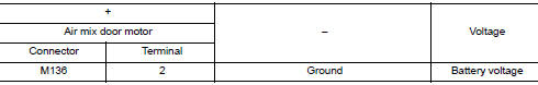
Is the inspection result normal? YES >> GO TO 3.
NO >> GO TO 2.
2.CHECK AIR MIX DOOR MOTOR POWER SUPPLY CIRCUIT FOR OPEN
- Disconnect front air control connector.
- Check continuity between air mix door motor harness connector and front air control harness connector.
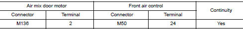
Is the inspection result normal? YES >> Replace front air control. Refer to HAC-181, "Removal and Installation".
NO >> Repair harness or connector.
3.CHECK AIR MIX DOOR MOTOR DRIVE SIGNAL CIRCUIT FOR OPEN
- Turn ignition switch OFF.
- Disconnect front air control connector.
- Check continuity between air mix door motor harness connector and front air control harness connector.
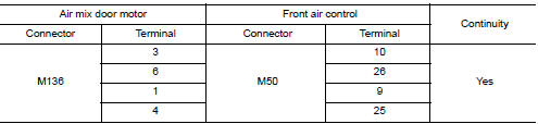
Is the inspection result normal? YES >> GO TO 4.
NO >> Repair harness or connector.
4.CHECK AIR MIX DOOR MOTOR DRIVE SIGNAL CIRCUIT FOR SHORT
Check continuity between air mix door motor harness connector and front air control harness connector.
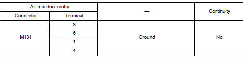
Is the inspection result normal? YES >> GO TO 5.
NO >> Repair harness or connector.
5.CHECK AIR MIX DOOR MOTOR
Check air mix door motor. Refer to HAC-164, "Component Inspection".
Is the inspection result normal? YES >> Replace front air control. Refer to HAC-181, "Removal and Installation".
NO >> Replace air mix door motor. Refer to HAC-185, "AIR MIX DOOR MOTOR : Removal and Installation".
Component Inspection
1.CHECK AIR MIX DOOR MOTOR
- Remove air mix door motor. Refer to HAC-185, "AIR MIX DOOR MOTOR : Removal and Installation".
- Check resistance between air mix door motor terminals. Refer to applicable table for the normal value.
Is the inspection result normal? YES >> Inspection End.
NO >> Replace air mix door motor. Refer to HAC-185, "AIR MIX DOOR MOTOR : Removal and Installation".
POWER SUPPLY AND GROUND CIRCUIT
FRONT A/C CONTROL
FRONT A/C CONTROL : Diagnosis Procedure
Regarding Wiring Diagram information, refer to HAC-136, "Wiring Diagram".
1.CHECK FUSE
Check 10A fuse [No. 20, located in the fuse block (J/B)].
NOTE: Refer to PG-64, "Terminal Arrangement".
Is the inspection result normal? YES >> GO TO 2.
NO >> Replace the blown fuse after repairing the affected circuit.
2.CHECK FRONT AIR CONTROL POWER SUPPLY
- Turn ignition switch OFF.
- Disconnect front air control connector.
- Check voltage between front air control harness connector and ground.
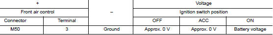
Is the inspection result normal? YES >> GO TO 3.
NO >> Repair harness or connector.
3.CHECK FRONT AIR CONTROL GROUND CIRCUIT
- Turn ignition switch OFF.
- Check continuity between front air control harness connector and ground.
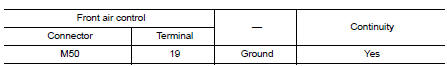
Is the inspection result normal? YES >> Inspection End.
NO >> Repair harness or connector.
FRONT BLOWER MOTOR
Diagnosis Procedure
Regarding Wiring Diagram information, refer to HAC-136, "Wiring Diagram".
1.CHECK FUSE
- Turn ignition switch OFF.
- Check 20A fuses [Nos. 17 and 27, located in fuse block (J/B)]
NOTE: Refer to PG-64, "Terminal Arrangement". Is the inspection result normal? YES >> GO TO 2.
NO >> Replace the blown fuse after repairing the affected circuit.
2.CHECK FRONT BLOWER MOTOR POWER SUPPLY
- Disconnect front blower motor connector.
- Turn ignition switch ON.
- Check voltage between front blower motor harness connector and ground.
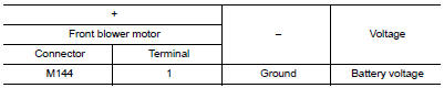
Is the inspection result normal? YES >> GO TO 4.
NO >> GO TO 3.
3.CHECK FRONT BLOWER RELAY
- Turn ignition switch OFF.
- Check front blower relay. Refer to HAC-170, "Component Inspection (Front Blower Relay)".
Is the inspection result normal? YES >> Repair harness or connector between front blower motor and fuse.
NO >> Replace front blower relay.
4.CHECK BLOWER MOTOR CONTROL CIRCUIT
- Turn ignition switch OFF.
- Connect front blower motor connector.
- Disconnect variable blower control connector.
- Turn ignition switch ON.
- Check voltage between variable blower control harness connector and ground.
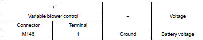
Is the inspection result normal? YES >> GO TO 6.
NO >> GO TO 5.
5.CHECK FRONT BLOWER MOTOR CONTROL CIRCUIT FOR OPEN
- Turn ignition switch OFF.
- Disconnect front blower motor connector.
- Check continuity between variable blower control harness connector and front blower motor harness connector.
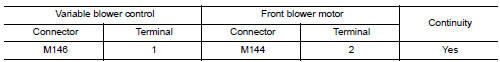
Is the inspection result normal? YES >> Replace front blower motor. Refer to VTL-16, "Removal and Installation".
NO >> Repair harness or connector.
6.CHECK VARIABLE BLOWER CONTROL GROUND CIRCUIT FOR OPEN
- Turn ignition switch OFF.
- Check continuity between variable blower control harness connector and ground.
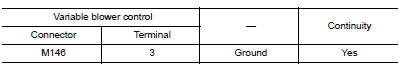
Is the inspection result normal? YES >> GO TO 7.
NO >> Repair harness or connector.
7.CHECK VARIABLE BLOWER CONTROL SIGNAL CIRCUIT
- Turn blower control dial fully counterclockwise to the OFF position
- While turning the blower control dial clockwise, through each detent, check voltage between variable blower control and ground.
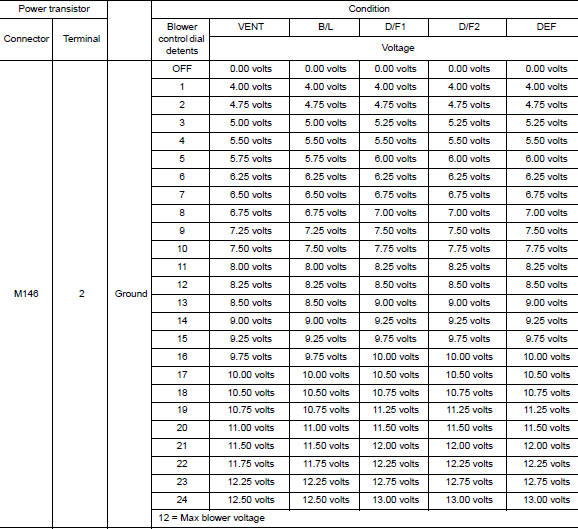
Is the inspection result normal? YES >> Replace variable blower control. Refer to HAC-187, "Removal and Installation".
NO >> GO TO 8.
8.CHECK VARIABLE BLOWER CONTROL SIGNAL CIRCUIT FOR OPEN
- Turn ignition switch OFF.
- Disconnect variable blower control connector and front air control connector.
- Check continuity between variable blower control harness connector and front air control harness connector.
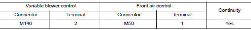
Is the inspection result normal? YES >> GO TO 9.
NO >> Repair harness or connector.
9.CHECK VARIABLE BLOWER CONTROL SIGNAL CIRCUIT FOR SHORT
Check continuity between variable blower control harness connector and ground.
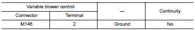
Is the inspection result normal? YES >> Replace front air control. Refer to HAC-181, "Removal and Installation".
NO >> Repair harness or connector.
Component Inspection (Front Blower Motor)
1.CHECK FRONT BLOWER MOTOR
- Connect battery voltage to terminal 1 of front blower motor.
- Connect ground to terminal 2 of front blower motor.
Does the blower fan operate? YES >> Intermittent incident. Refer to GI-41, "Intermittent Incident".
NO >> Replace front blower motor. Refer to VTL-16, "Removal and Installation".
Component Inspection (Front Blower Relay)
1.CHECK FRONT BLOWER RELAY
- Turn ignition switch OFF.
- Remove front blower relay.
- Check continuity between front blower relay terminals 3 and 5 when voltage is supplied between terminals 1 and 2.
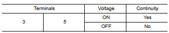
Is the inspection result normal? YES >> Inspection End.
NO >> Replace front blower relay.
MAGNET CLUTCH
Component Function Check
1.CHECK MAGNET CLUTCH OPERATION
Perform тАЬCOMPRESSORтАЭ тАЬActive TestтАЭ of тАЬIPDM E/RтАЭ. Refer to HAC-129, "CONSULT Function (IPDM E/R)".
Does it operate normally? YES >> Inspection End.
NO >> Refer to HAC-171, "Diagnosis Procedure".
Diagnosis Procedure
Regarding Wiring Diagram information, refer to HAC-136, "Wiring Diagram".
1.CHECK FUSE
- Turn ignition switch OFF.
- Check 15A fuse (No. 40, located in IPDM E/R).
NOTE: Refer to PG-68, "IPDM E/R Terminal Arrangement". Is the inspection result normal? YES >> GO TO 2.
NO >> Replace the blown fuse after repairing the affected circuit.
2.CHECK MAGNET CLUTCH POWER SUPPLY CIRCUIT
- Disconnect compressor connector and IPDM E/R connector.
- Check continuity between compressor harness connector and IPDM E/R harness connector.
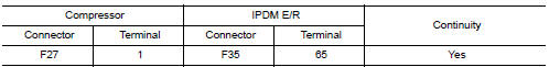
Is the inspection result normal? YES >> GO TO 3.
NO >> Repair harness or connector.
3.CHECK MAGNET CLUTCH GROUND CIRCUIT
- Disconnect compressor connector.
- Check continuity between compressor harness connector and ground.
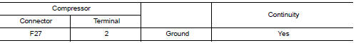
Is the inspection result normal? YES >> GO TO 4.
NO >> Repair harness or connector.
4.CHECK MAGNET CLUTCH
Directly apply battery voltage to the magnet clutch. Check operation visually and by sound.
Does it operate normally? YES >> Replace IPDM E/R. Refer to PCS-35, "Removal and Installation".
NO >> Replace magnet clutch. Refer to HA-30, "Removal and Installation".
ECV (ELECTRICAL CONTROL VALVE)
Diagnosis Procedure
Regarding Wiring Diagram information, refer to HAC-136, "Wiring Diagram".
1.CHECK ECV (ELECTRICAL CONTROL VALVE) POWER SUPPLY
- Turn ignition switch OFF.
- Disconnect compressor connector.
- Turn ignition switch ON.
- Check voltage between compressor harness connector and ground.
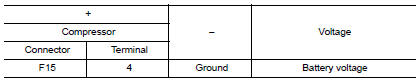
Is the inspection result normal? YES >> GO TO 3.
NO >> GO TO 2.
2.CHECK FUSE
- Turn ignition switch OFF.
- Check 10 A fuse [No. 50, located in IPDM E/R]. Refer to PG-68, "IPDM E/R Terminal Arrangement".
Is the inspection result normal? YES >> Repair harness or connector.
NO >> Replace the blown fuse after repairing the affected circuit.
3.CHECK ECV CONTROL SIGNAL CIRCUIT FOR OPEN
- Turn ignition switch OFF.
- Disconnect IPDM E/R connector.
- Check continuity between compressor harness connector and IPDM E/R harness connector.
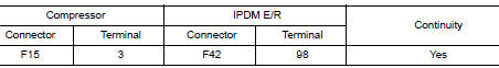
Is the inspection result normal? YES >> GO TO 4.
NO >> Repair harness or connector.
4.CHECK ECV CONTROL SIGNAL CIRCUIT FOR SHORT
Check continuity between compressor harness connector and ground.
Is the inspection result normal? YES >> GO TO 5.
NO >> Repair harness or connector.
5.CHECK ECV
Check ECV. Refer to HAC-173, "Component Inspection".
Is the inspection result normal? YES >> GO TO 6.
NO >> Replace compressor. Refer to HA-30, "Removal and Installation".
6.CHECK INTERMITTENT INCIDENT
Refer to GI-41, "Intermittent Incident".
Is the inspection result normal? YES >> Replace front air control. Refer to HAC-181, "Removal and Installation".
NO >> Repair or replace malfunctioning parts.
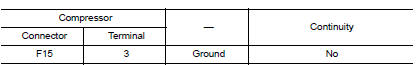
Component Inspection
1.CHECK ECV (ELECTRICAL CONTROL VALVE)
- Turn ignition switch OFF.
- Disconnect compressor connector.
- Check continuity between compressor connector F27 terminals.
Is the inspection result normal? YES >> Inspection End.
NO >> Replace compressor. Refer to HA-30, "Removal and Installation".
 Basic inspection
DIAGNOSIS AND REPAIR WORKFLOW
Work Flow
OVERALL SEQUENCE
DETAILED FLOW
1.INTERVIEW CUSTOMER
Interview the customer to obtain as much information as possible about the
conditions and environ ...
 Symptom diagnosis
HEATER AND AIR CONDITIONING SYSTEM CONTROL SYMPTOMS
Symptom Table
SYMPTOM TABLE
Symptom
Reference Page
A/C system does not come on.
Go to Trouble Diagnosis Procedure f ...
Other materials:
Front wiper auto stop signal circuit
Component Function Check
1. CHECK FRONT WIPER (AUTO STOP) SIGNAL
Select FR WIPER STOP of BCM (WIPER) data monitor item.
Operate the front wiper.
Check that FR WIPER STOP changes from ON to OFF according to the
wiper position
Is the inspection result normal?
YES ...
Precaution
Precaution for Supplemental Restraint System (SRS) "AIR BAG" and "SEAT
BELT
PRE-TENSIONER"
The Supplemental Restraint System such as тАЬAIR BAGтАЭ and тАЬSEAT BELT
PRE-TENSIONERтАЭ, used along
with a front seat belt, helps to reduce the risk or severity of injury to the
...
Unit disassembly and assembly
COMBINATION METER
Exploded View
Combination meter
Combination meter lens
Pawl
Disassembly and Assembly
CAUTION:
Do not touch the display, pointer, inside of combination meter
or the printed area of the dial during
disassembly or assembly.
Keep away from magn ...
