Nissan Rogue Service Manual: Diagnosis system (combination meter)
Description
COMBINATION METER SELF-DIAGNOSIS MODE
The following meter functions can be checked during Combination Meter Self-Diagnosis Mode:
- Pointer sweep of speedometer, tachometer and gauges.
- Illumination of all LCD segments and color patterns for meter displays.
- Illumination of all lamps/LEDs that are controlled by the combination meter (regardless of switch status).
STARTING COMBINATION METER SELF-DIAGNOSIS MODE
NOTE:
- Check combination meter power supply and ground circuits if self-diagnosis mode does not start. Refer to MWI-59, "COMBINATION METER : Diagnosis Procedure". Replace combination meter if power supply and ground circuits are found to be normal and self-diagnosis mode does not start. Refer to MWI-82, "Removal and Installation".
- Combination meter self-diagnosis mode will function with the ignition switch in ON. Combination meter selfdiagnosis mode will exit upon turning the ignition switch to OFF.
How to Initiate Self-Diagnosis Mode
- Turn ignition switch OFF.
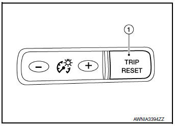
- While pressing the trip reset switch (1), turn ignition switch ON.
- Keep the trip reset switch for 1 seconds or more.
- Press the trip reset switch at least 3 times. (Within 7 seconds after the ignition switch is turned ON.)
- ŌĆ£Work instruction codeŌĆØ is indicated in the top portion of information display and self-diagnosis is started.
- The mode switches in the order shown below each time the trip
reset switch is pressed.
NOTE: If the trip reset switch is not operated for 20 seconds or more, the self-diagnosis mode is automatically cancelled.
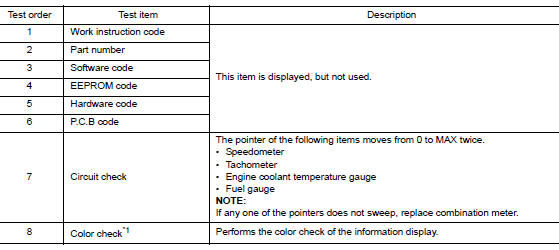
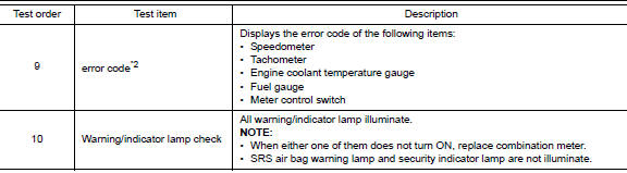
NOTE: When the trip reset switch is pressed during the indication of Test order ŌĆ£10,ŌĆØ test item returns to Test order ŌĆ£2.ŌĆØ
*1: Color Check
- Blue
- Red
- Pink
- Green
- Light blue
- Yellow
- White
- White
- Black
- Light blue
- Black
- Pink
- Black
- Blue
- Black
- Dark blue
- White
- Blue
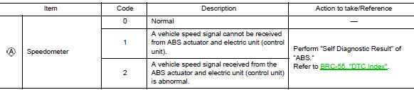
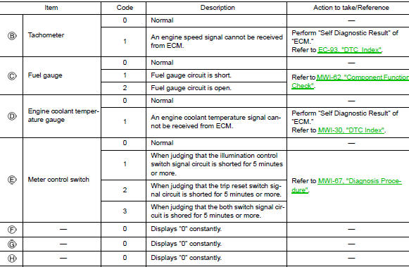
*2: Error Code
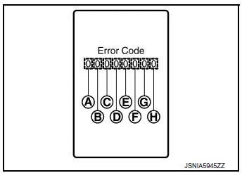
How to Reset Error Code
Error codes stored in combination meter can be reset by following the instructions below:
- Turn ignition switch OFF.
- While pressing the trip reset switch, turn ignition switch ON.
- Keep the trip reset switch for 1 seconds or more.
- Press the trip reset switch at least 3 times. (Within 7 seconds after the ignition switch is turned ON.)
- Turn ignition switch OFF.
- Perform self-diagnosis and check that the error codes are reset.
CONSULT Function (METER/M&A)
APPLICATION ITEMS
CONSULT can display each diagnostic item using the diagnostic test modes shown.
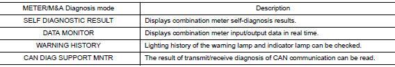
SELF DIAG RESULT
Refer to MWI-30, "DTC Index".
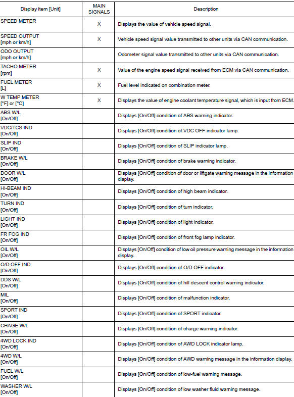
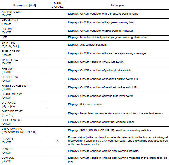
DATA MONITOR
Display Item List
SPECIAL FUNCTION
Special menu

W/L ON HISTORY
- ŌĆ£W/L ON HISTORYŌĆØ indicates the ŌĆ£TIMEŌĆØ when the warning/ indicator lamp is turned on.
- The ŌĆ£TIMEŌĆØ above is:
- 0: The condition that the warning/indicator lamp has been turned on 1 or more times after starting the engine and waiting for 30 seconds.
- 1 - 39: The number of times the engine was restarted after the 0 condition.
- NO W/L ON HISTORY: No warning/indicator lamp history is stored.
NOTE:
- W/L ON HISTORY is not stored for approximately 30 seconds after the engine starts.
- Brake warning lamp does not store any history when the parking brake is applied or the brake fluid level gets low.
 System
WARNING CHIME SYSTEM
WARNING CHIME SYSTEM : System Description
SYSTEM DIAGRAM (WITH INTELLIGENT KEY SYSTEM)
SYSTEM DIAGRAM (WITHOUT INTELLIGENT KEY SYSTEM)
COMBINATION METER INPUT/OUTPUT S ...
 Diagnosis system (BCM) (with intelligent key system)
COMMON ITEM
COMMON ITEM : CONSULT Function (BCM - COMMON ITEM)
APPLICATION ITEM
CONSULT performs the following functions via CAN communication with BCM.
SYSTEM APPLICATION
BCM can perform the ...
Other materials:
P084c transmission fluid pressure SEN/SW H
DTC Description
DTC DETECTION LOGIC
DTC
CONSULT screen terms
(Trouble diagnosis content)
DTC detection condition
P084C
FLUID PRESS SEN/SW H
(Transmission Fluid Pressure Sensor/Switch H
Circuit Low)
When all of the following conditions are satisfied and this sta ...
Component parts
MOONROOF
MOONROOF : Component Parts Location
Moonroof switch
View with headliner removed
Combination meter
Behind instrument panel (LH)
View with LH door open (RH similiar)
MOONROOF : Component Description
No
Component
Function
1
Moonroof swi ...
The fuel gauge does not move
Description
Fuel gauge does not move from a certain position.
Diagnosis Procedure
1.CONDUCTING THE COMBINATION METER SELF-DIAGNOSIS MODE
Perform the self-diagnosis mode of combination meter, and then check that the
fuel gauge operates normally.
Refer to MWI-19, "Description".
I ...
