Nissan Rogue Service Manual: Brake pedal position switch
Component Function Check
1.CHECK BRAKE PEDAL POSITION SWITCH FUNCTION
 With CONSULT
- Turn ignition switch ON.
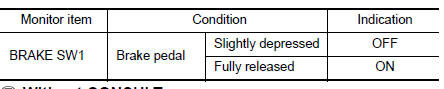
- Select “BRAKE SW1” in “DATA MONITOR” mode with CONSULT.
- Check “BRAKE SW1” indication as per the following conditions.
 Without CONSULT
- Turn ignition switch ON.
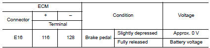
- Check the voltage between ECM harness connector terminals.
Is the inspection result normal? YES >> INSPECTION END
NO >> Proceed to EC-455, "Diagnosis Procedure".
Diagnosis Procedure
1.CHECK BRAKE PEDAL POSITION SWITCH POWER SUPPLY CIRCUIT
- Turn ignition switch OFF.
- Disconnect brake pedal position switch harness connector.
- Turn ignition switch ON.
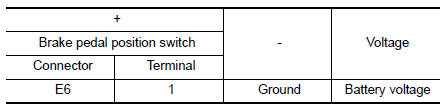
- Check the voltage between brake pedal position switch harness connector and ground.
Is the inspection result normal? YES >> GO TO 3.
NO >> GO TO 2.
2.CHECK BRAKE PEDAL POSITION SWITCH POWER SUPPLY CIRCUIT
- Turn ignition switch OFF.
- Disconnect fuse block (J/B) harness connector.
- Check the continuity between brake pedal position switch harness connector and fuse block (J/B) harness connector.
Is the inspection result normal? YES >> Perform the trouble diagnosis for power supply circuit.
NO >> Repair or replace error-detected parts.
3.CHECK BRAKE PEDAL POSITION SWITCH INPUT SIGNAL CIRCUIT
- Turn ignition switch OFF.
- Disconnect ECM harness connector.
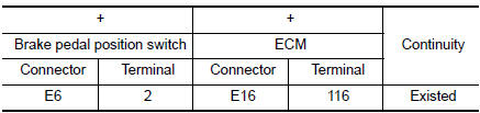
- Check the continuity between brake pedal position switch harness connector and ECM harness connector.
- Also check harness for short to ground and to power.
Is the inspection result normal? YES >> GO TO 4.
NO >> Repair open circuit, short to ground or short to power in harness or connectors.
4.CHECK BRAKE PEDAL POSITION SWITCH
Check brake pedal position switch. Refer to EC-456, "Component Inspection (Brake Pedal Position Switch)".
Is the inspection result normal? YES >> Check intermittent incident. Refer to GI-41, "Intermittent Incident".
NO >> Replace brake pedal position switch. Refer to BR-20, "Exploded View".
Component Inspection (Brake Pedal Position Switch)
1.CHECK BRAKE PEDAL POSITION SWITCH-1
- Turn ignition switch OFF.
- Disconnect brake pedal position harness connector.
- Check the continuity between brake pedal position switch terminals as per the following conditions.
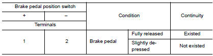
Is the inspection result normal? YES >> INSPECTION END
NO >> GO TO 2.
2.CHECK BRAKE PEDAL POSITION SWITCH-2
- Adjust brake pedal position switch installation. Refer to BR-15, "Adjustment".
- Check the continuity between brake pedal position switch terminals as per the following conditions.
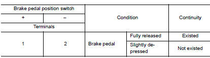
Is the inspection result normal?
YES >> INSPECTION END
NO >> Replace brake pedal position switch. Refer to BR-20, "Exploded View".
 P2610 ECM internal timer
Description
This ECM contains a timer and measures time between an ignition switch OFF
and the next ignition switch
ON. This enables the judging of the state of engine cooling at an engine start.
...
 Cooling fan
Component Function Check
1.CHECK COOLING FAN FUNCTION
With CONSULT
Turn ignition switch ON.
Perform “COOLING FAN (DUAL)” in “ACTIVE TEST” mode of “IPDM E/R”
using CO ...
Other materials:
Tire pressure sensor
Exploded View
Tire pressure sensor
O-ring
Valve stem nut
Valve core
Valve cap
Valve stem assembly
: Parts that are replaced as a
set when the tire is replaced.
Removal and Installation
REMOVAL
Remove wheel and tire using power tool.
Remove v ...
P0890 TCM
DTC Description
DTC DETECTION LOGIC
DTC
CONSULT screen terms
(Trouble diagnosis content)
DTC detection condition
P0890
TCM
(Transmission Control Module Power Relay
Sense Circuit Low)
When all of the following conditions are satisfied and this state is
maint ...
Repairing material
Foam Repair
During factory body assembly, foam insulators are installed in certain body
panels and locations around the
vehicle. Use the following procedure(s) to replace any factory-installed foam
insulators.
URETHANE FOAM APPLICATIONS
Use commercially available Urethane foam for sealant (f ...
