Nissan Rogue Owners Manual: Booster seats
Precautions on booster seats
| WARNING If a booster seat and seat belt are not used properly, the risk of a child being injured in a sudden stop or collision greatly increases:
|
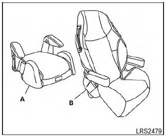
- Low back booster seat
- High back booster seat
Booster seats of various sizes are offered by several manufacturers. When selecting any booster seat, keep the following points in mind:
- Choose only a booster seat with a label certifying that it complies with Federal Motor Vehicle Safety Standard 213 or Canadian Motor Vehicle Safety Standard 213.
- Check the booster seat in your vehicle to be sure it is compatible with the vehicle’s seat and seat belt system.
- Make sure the child’s head will be properly supported by the booster seat or vehicle seat. The seatback must be at or above the center of the child’s ears. For example, if a low back booster seat is chosen, the vehicle seatback must be at or above the center of the child’s ears. If the seatback is lower than the center of the child’s ears, a high back booster seat should be used.
- If the booster seat is compatible with your vehicle, place the child in the booster seat and check the various adjustments to be sure the booster seat is compatible with the child. Always follow all recommended procedures.
All U.S. states and Canadian provinces or territories require that infants and small children be restrained in an approved child restraint at all times while the vehicle is being operated. The instructions in this section apply to booster seat installation in the rear seats or the front passenger seat.
Booster seat installation
| CAUTION Do not use the lap/shoulder belt in the Automatic Locking Retractor (ALR) mode when using a booster seat with the seat belts. |
For additional information, refer to all Warnings and Cautions in the “Child Safety,” “Child Restraint” and “Booster Seats” sections before installing a child restraint.
Follow these steps to install a booster seat in the 2nd or 3rd rows or in the front passenger seat:
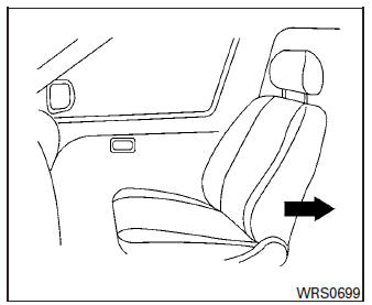
- If you must install a booster seat in the front seat, move the seat to the rearmost position.
- Position the booster seat on the seat. Only place it in a front-facing direction. Always follow the booster seat manufacturer’s instructions.
Front passenger position
- The booster seat should be positioned on the vehicle seat so that it is stable.
If necessary, adjust or remove the head restraint/headrest to obtain the correct booster seat fit. If the head restraint/headrest is removed, store it in a secure place. Be sure to reinstall the head restraint/headrest when the booster seat is removed. For additional information, refer to “Head restraints/headrests” in this section for head restraint/headrest adjustment, removal and installation information.
If the seating position does not have an adjustable head restraint/headrest and it is interfering with the proper booster seat fit, try another seating position or a different booster seat.
- Position the lap portion of the seat belt low and snug on the child’s hips. Be sure to follow the booster seat manufacturer’s instructions for adjusting the seat belt routing.
- Pull the shoulder belt portion of the seat belt
toward the retractor to take up extra slack.
Be sure the shoulder belt is positioned across the top, middle portion of the child’s shoulder. Be sure to follow the booster seat manufacturer’s instructions for adjusting the seat belt routing.
- Follow the warnings, cautions and instructions for properly fastening a seat belt shown in “Three-point type seat belt with retractor” in this section.
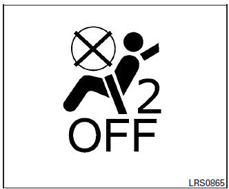
- If the booster seat is installed in the front
passenger seat, place the ignition switch in
the ON position. The front passenger air bag
status light
 may or may not
illuminate,
depending on the size of the child and the
type of booster seat being used. For additional
information, refer to “Front passenger
air bag and status light” in this section.
may or may not
illuminate,
depending on the size of the child and the
type of booster seat being used. For additional
information, refer to “Front passenger
air bag and status light” in this section.
 Forward-facing child restraint installation
using the seat belts
Forward-facing child restraint installation
using the seat belts
WARNINGThe three-point seat belt with Automatic
Locking Retractor (ALR) must be used
when installing a child restraint. Failure to
use the ALR mode will result in the child
restrain ...

Other materials:
C1197 vacuum sensor
DTC Logic
DTC DETECTION LOGIC
DTC
Display Item
Malfunction detected condition
Possible causes
C1197
VACUUM SENSOR
When a malfunction is detected in vacuum sensor.
Harness or connector
Vacuum sensor (brake booster)
Vacuum piping
&nb ...
U1000 CAN COMM CIRCUIT
Description
CAN communication allows a high rate of information transmission through the
two communication lines
(CAN-H line and CAN-L line) connecting various control units in the system. Each
control unit transmits/
receives data but selectively reads required data only.
DTC Logic
DTC DET ...
Removal and installation
BCM (BODY CONTROL MODULE)
Removal and Installation
CAUTION:
Before replacing the BCM, perform “READ CONFIGURATION” to save or print current
vehicle specification.
Refer to BCS-120, "ADDITIONAL SERVICE WHEN REPLACING CONTROL UNIT (BCM) : Work
Procedure".
REMOVAL
Disc ...
