Nissan Rogue Service Manual: Basic inspection
DIAGNOSIS AND REPAIR WORKFLOW
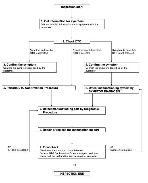
Work Flow
OVERALL SEQUENCE

DETAILED FLOW
1.GET INFORMATION FOR SYMPTOM
Get the detailed information from the customer about the symptom (the condition and the environment when the incident/malfunction occurred).
>> GO TO 2.
2.CHECK DTC
- Check DTC.
- Perform the following procedure if DTC is displayed.
- Record DTC and freeze frame data (Print them out with CONSULT.)
- Erase DTC.
- Study the relationship between the cause detected by DTC and the symptom described by the customer.
- Check related service bulletins for information.
Is any symptom described and any DTC detected? Symptom is described, DTC is displayed>>GO TO 3.
Symptom is described, DTC is not displayed>>GO TO 4.
Symptom is not described, DTC is displayed>>GO TO 5.
3.CONFIRM THE SYMPTOM
Confirm the symptom described by the customer.
Connect CONSULT to the vehicle in “DATA MONITOR” mode and check real time diagnosis results.
Verify relation between the symptom and the condition when the symptom is detected.
>> GO TO 5.
4.CONFIRM THE SYMPTOM
Confirm the symptom described by the customer.
Connect CONSULT to the vehicle in “DATA MONITOR ” mode and check real time diagnosis results.
Verify relation between the symptom and the condition when the symptom is detected.
>> GO TO 6.
5.PERFORM DTC CONFIRMATION PROCEDURE
Perform DTC Confirmation Procedure for the displayed DTC, and then check that DTC is detected again.
At this time, always connect CONSULT to the vehicle, and check diagnostic results in real time.
If two or more DTCs are detected, refer to BCS-107, "DTC Inspection Priority Chart" and determine trouble diagnosis order.
NOTE:
- Freeze frame data is useful if the DTC is not detected.
- Perform Component Function Check if DTC Confirmation Procedure
is not included in Service Manual. This
simplified check procedure is an effective alternative though DTC cannot be
detected during this check.
If the result of Component Function Check is NG, it is the same as the detection of DTC by DTC Confirmation Procedure.
Is DTC detected? Yes >> GO TO 7.
No >> Refer to GI-41, "Intermittent Incident".
6.DETECT MALFUNCTIONING SYSTEM BY SYMPTOM TABLE
Detect malfunctioning system according to SYMPTOM TABLE based on the confirmed symptom in step 4, and determine the trouble diagnosis order based on possible causes and symptom.
>> GO TO 7.
7.DETECT MALFUNCTIONING PART BY DIAGNOSTIC PROCEDURE
Inspect according to Diagnostic Procedure of the system.
NOTE: The Diagnostic Procedure described based on open circuit inspection. A short circuit inspection is also required for the circuit check in the Diagnostic Procedure. Is malfunctioning part detected? YES >> GO TO 8.
NO >> Check voltage of related BCM terminals using CONSULT.
8.REPAIR OR REPLACE THE MALFUNCTIONING PART
- Repair or replace the malfunctioning part.
- Reconnect parts or connectors disconnected during Diagnostic Procedure again after repair and replacement.
- Check DTC. If DTC is displayed, erase it.
>> GO TO 9.
9.FINAL CHECK
When DTC was detected in step 2, perform DTC Confirmation Procedure or Component Function Check again, and then check that the malfunction have been repaired securely.
When symptom was described from the customer, refer to confirmed symptom in step 3 or 4, and check that the symptom is not detected.
Is the inspection result normal? NO (DTC is detected)>>GO TO 7.
NO (Symptom remains)>>GO TO 6.
YES >> Inspection End.
INSPECTION AND ADJUSTMENT
ADDITIONAL SERVICE WHEN REPLACING CONTROL UNIT
ADDITIONAL SERVICE WHEN REPLACING CONTROL UNIT : Description
Perform the system initialization when replacing BCM, replacing keyfob or registering an additional keyfob.
ADDITIONAL SERVICE WHEN REPLACING CONTROL UNIT : Special Repair Requirement
Refer to the CONSULT Immobilizer mode and follow the on-screen instructions.
 Wiring diagram
POWER DOOR LOCK SYSTEM
Wiring Diagram
REMOTE KEYLESS ENTRY SYSTEM
Wiring Diagram
...
 DTC/circuit diagnosis
U1000 CAN COMM CIRCUIT
Description
Refer to LAN-8, "System Description".
DTC Logic
DTC DETECTION LOGIC
NOTE:
U1000 can be set if a module harness was disconnected and reconnected, perh ...
Other materials:
Operating range
Operating range
The Intelligent Key functions can only be used
when the Intelligent Key is within the specified
operating range from the request switch 1 .
When the Intelligent Key battery is discharged or
strong radio waves are present near the operating
location, the Intelligent Key op ...
Front disc brake
BRAKE CALIPER ASSEMBLY (1 PISTON TYPE)
BRAKE CALIPER ASSEMBLY (1 PISTON TYPE) : Exploded View
Torque member
Bushing
Piston boot
Slide pin boot
Slide pin
Piston
Piston seal
Brake caliper body
Bleeder cap
Brake hose
Copper sealing washers
...
Three-point type seat belt with retractor
WARNING
Every person who drives or rides in this
vehicle should use a seat belt at all
times.
Do not ride in a moving vehicle when
the seatback is reclined. This can be
dangerous. The shoulder belt will not
be against your body. In an accident,
you ...
