Nissan Rogue Service Manual: B0001, B0002 driver airbag module
DTC Logic
DTC DETECTION LOGIC
|
CONSULT name |
DTC |
DTC detecting condition |
Repair order |
| DRIVER AIRBAG MODULE CIRCUIT [OPEN] | B0001 | Driver air bag module circuit (DR1) is open (including the spiral cable). | Refer to SRC-47, "Diagnosis Procedure". |
| DRIVER AIRBAG MODULE CIRCUIT [VB-SHORT] | Driver air bag module circuit (DR1) is shorted to a power supply circuit (including the spiral cable). | ||
| DRIVER AIRBAG MODULE CIRCUIT [GND-SHORT] | Driver air bag module circuit (DR1) is shorted to ground (including the spiral cable). | ||
| DRIVER AIRBAG MODULE CIRCUIT [SHORT] | Driver air bag module circuits (DR1) are shorted to each other (including the spiral cable) | ||
| DRIVER AIRBAG MODULE 2ND CIRCUIT [OPEN] | B0002 | Driver air bag module circuit (DR2) is open (including the spiral cable). | |
| DRIVER AIRBAG MODULE 2ND CIRCUIT [VB-SHORT] | Driver air bag module circuit (DR2) is shorted to a power supply circuit (including the spiral cable | ||
| DRIVER AIRBAG MODULE 2ND CIRCUIT [GND-SHORT] | Driver air bag module circuit (DR2) is shorted to ground (including the spiral cable). | ||
| DRIVER AIRBAG MODULE 2ND CIRCUIT [SHORT] | Driver air bag module circuits (DR2) are shorted to each other (including the spiral cable). |
DTC CONFIRMATION PROCEDURE (With CONSULT)
1.CHECK SELF-DIAG RESULT
- Turn ignition switch ON.
- Check for DTC using CONSULT.
Is the DTC detected? YES (Current DTC)>>Refer to SRC-47, "Diagnosis Procedure".
YES (Past DTC)>>GO TO 2.
NO >> Inspection End.
2.ERASE SELF-DIAG RESULT
Erase the DTC using CONSULT.
Can the DTC be erased? YES >> Inspection End.
NO >> Refer to SRC-47, "Diagnosis Procedure".
DTC CONFIRMATION PROCEDURE (Without CONSULT)
1.CHECK SELF-DIAG RESULT
- Turn ignition switch ON.
- Check the air bag warning lamp status. Refer to SRC-16, "On Board Diagnosis Function".
NOTE: SRS will not enter diagnosis mode if no malfunction is detected in user mode.
Is the DTC detected? YES >> Refer to SRC-47, "Diagnosis Procedure".
NO >> Inspection End.
Diagnosis Procedure
WARNING:
- Before servicing, turn ignition switch OFF, disconnect battery negative terminal, and wait 3 minutes or more. (To discharge backup capacitor.)
- Never use unspecified tester or other measuring device.
1.HARNESS CONNECTOR
Visually inspect all applicable harness connectors for the following:
- Visible damage to connector or terminal
- Loose terminal
- Poor connection
NOTE: All harness connectors should be inspected from the air bag diagnosis unit to the end component (including any in-line connectors). Is the inspection result normal? YES >> GO TO 2.
NO >> Perform one of the following repairs:
- Visible damage: Replace the harness.
- Loose terminal: Secure the terminal.
- Poor connection: Secure the connection.
2.CONFIRM DTC
- Reconnect all harness connectors.
- Turn ignition switch ON.
- Check for DTC using CONSULT.
Is DTC still current? YES >> GO TO 3.
NO >> Refer to GI-41, "Intermittent Incident".
3.WIRING HARNESS
Check the wiring harness for visible damage.
NOTE: The entire wiring harness should be inspected from the air bag diagnosis sensor unit to the end component (including any in-line connectors).
Is the inspection result normal? YES >> GO TO 4.
NO >> Replace the harness.
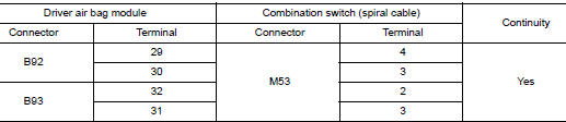
4.CHECK SPIRAL CABLE CIRCUIT
- Turn ignition switch OFF.
- Disconnect driver air bag module harness connector and combination switch (spiral cable) harness connector.
- Check continuity between driver air bag module harness connector and combination switch (spiral cable) harness connector.
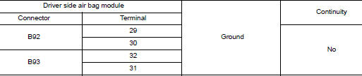
- Check continuity between driver air bag module harness connector and ground.
Is the inspection result normal? YES >> GO TO 5.
NO >> Replace combination switch (spiral cable). Refer to SR-15, "Removal and Installation".
5.CONFIRM DTC
- Reconnect all harness connectors.
- Turn ignition switch ON.
- Check for DTC using CONSULT.
Is DTC still current? YES >> GO TO 6.
NO >> Refer to GI-41, "Intermittent Incident".
6.AIR BAG DIAGNOSIS SENSOR UNIT
- Replace the air bag diagnosis sensor unit. Refer to SR-26, "Removal and Installation".
- Turn ignition switch ON.
- Check for DTC using CONSULT.
Is DTC still current? YES >> GO TO 7.
NO >> Clear DTC. Inspection End.
7.DRIVER AIR BAG MODULE
- Replace the driver air bag module. Refer to SR-12, "Removal and Installation".
- Turn ignition switch ON.
- Check for DTC using CONSULT.
Is DTC still current? YES >> GO TO 8.
NO >> Clear DTC. Inspection End.
8.RELATED HARNESS
Replace the related harness.
>> END

 B0010, B0011 passenger airbag module
DTC Logic
DTC DETECTION LOGIC
CONSULT name
DTC
DTC detecting condition
Repair order
ASSIST AIRBAG MODULE CIRCUIT
[OPEN]
B0010
Front passenger air ba ...
Other materials:
Main power window and door lock/unlock switch
Removal and Installation
REMOVAL
Remove the front door pull handle bracket (LH). Refer to INT-15,
"Removal and Installation".
Release pawls using a suitable tool (A) and remove main power
window and door lock/unlock switch finisher (1).
: Pawl
Disconnect t ...
CAN system (type 3)
MAIN LINE BETWEEN IPDM-E AND DLC CIRCUIT
Diagnosis Procedure
1.CHECK CONNECTOR
Turn the ignition switch OFF.
Disconnect the battery cable from the negative terminal.
Check the following terminals and connectors for damage, bend and
loose connection (connector side
and harn ...
Additional service when replacing ECM
Description
When replacing ECM, the following procedure must be performed. (For details,
refer to EC-136, "Work Procedure".)
PROGRAMMING OPERATION
NOTE:
After replacing with a blank ECM, programming is required to write ECM
information. Be sure to follow the procedure
to perform t ...
